Calibration method and system for non-orthogonal error of gyroscope

A technology of quadrature error and calibration method, applied in the direction of instruments, measuring devices, etc., can solve the problems of inability to eliminate installation errors, equipment measurement errors, installation errors, etc., and achieve the effect of improving accuracy and improving accuracy

Active Publication Date: 2019-11-05
HANGZHOU DIANZI UNIV +1
View PDF7 Cites 2 Cited by
  • Summary
  • Abstract
  • Description
  • Claims
  • Application Information

AI Technical Summary

Benefits of technology

This patented technology allows for precise measurements with an improved way that uses only two axes instead of three or four. It involves mounting the sensor onto a panel where it's pointing towards another surface called a base plate. By controlling both angles simultaneously, any changes made along different directions are detected accurately. These techniques help reduce interference from other sources like gravity waves caused by movement during use. Overall, this innovation helps ensure high precision performance over time while reducing costs associated therewith.

Problems solved by technology

This patents describes how different types of sensors like those found inside an electronics product have their characteristics that change with time due to changes overtime or environmental conditions. When these sensor values vary from initial settings they may result in incorrect calculations for calculating angles without being corrected during operation. Additionally, there could even exist issues related to mounting them correctly onto specific parts of the system causing further complications.

Method used


Image

  • Calibration method and system for non-orthogonal error of gyroscope
  • Calibration method and system for non-orthogonal error of gyroscope
  • Calibration method and system for non-orthogonal error of gyroscope

Examples


Embodiment Construction

[0018] The following will clearly and completely describe the technical solutions in the embodiments of the present invention with reference to the accompanying drawings in the embodiments of the present invention. Obviously, the described embodiments are some of the embodiments of the present invention, but not all of them. Based on the embodiments of the present invention, all other embodiments obtained by persons of ordinary skill in the art without making creative efforts belong to the protection scope of the present invention.

[0019] It should be understood that when used in this specification and the appended claims, the terms "comprising" and "comprises" indicate the presence of described features, integers, steps, operations, elements and / or components, but do not exclude one or The presence or addition of multiple other features, integers, steps, operations, elements, components and / or collections thereof.

[0020] It should also be understood that the terminology


PUM


Abstract

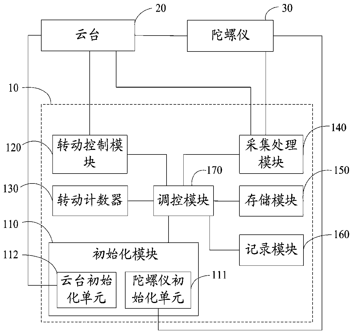
The invention discloses a calibration method and system for a non-orthogonal error of a gyroscope. The method comprises the steps that step S110, each axial non-orthogonal error of the gyroscope on aninitialized cradle head is zero, and each joint angle of each shaft of the cradle head is controlled at an initial zero position; S120, one shaft of the cradle head is controlled to rotate a preset angle in the corresponding axial direction, and the rotation frequency is updated; step 130, a change value of the joint angle of each shaft of the cradle head and each axial angular velocity measuredby the gyroscope are acquired, an axial non-orthogonal error of a rotating shaft is calculated, and each axial angular velocity is calibrated; S140, whether or not preset conditions are met is judged,if not, S120 is returned to be executed; if yes, the shaft is controlled to return to the initial zero position; S150, whether or not the calibration of each shaft is completed is judged, and if not,other shafts are controlled to be subjected to S120-S140, and if yes, ending is conducted. The calibration method and system for the non-orthogonal error of the gyroscope directly calibrate the non-orthogonal error by arranging the gyroscope on the cradle head to avoid the influence of the installation error.

Description


Claims


Application Information

Patent Timeline
Owner HANGZHOU DIANZI UNIV
Why Eureka
Try Eureka