Video streaming system and method
A video stream and stream transmission technology, applied in the field of video transmission, can solve the problems of poor user satisfaction, high bandwidth, low delay, etc., and achieve the effect of improving satisfaction and increasing stability
- Summary
- Abstract
- Description
- Claims
- Application Information
AI Technical Summary
Problems solved by technology
Method used
Image


Examples
Embodiment 1
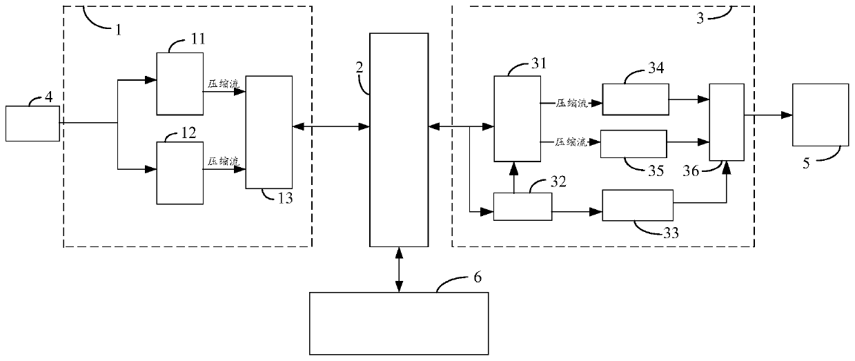
[0030] The embodiment of the present invention provides a video stream transmission system, see figure 1 A structural diagram of a video stream transmission system shown, including: a video encoding sender 1, a switch 2, and a video decoding receiver 3;
[0031] The video encoding sending end 1 is used to encode the received video stream into shallow compressed video stream and deep compressed video stream, and send the shallow compressed video stream and deep compressed video stream to switch 2 .
[0032]The video encoding sender refers to a device that receives a video stream and encodes the received video stream. Encoding can be understood as compressing the video stream according to different compression ratios. Generally speaking, the video coding sending end is communicatively connected with an external signal source. The signal source sends an unencoded video stream to the video coding sender. After receiving the video stream, the video coder sender performs shallow compr
Embodiment 2
[0040] Embodiment 2 of the present invention provides another video stream transmission system, see figure 2 The structural diagram of another video streaming transmission system is shown, such as figure 2 Shown:
[0041] figure 2 The video coding sending end 1 in comprises deep compression module 11, shallow compression module 12 and first network control module 13; Deep compression module 11 and shallow compression module 12 are arranged between external signal source 4 and first network control module 13 ; The first network control module 13 communicates with the switch 2 .
[0042] The deep compression module 11 is used to compress the video stream sent by the signal source 4 into a deep compressed video stream; and send the deep compressed video stream to the first network control module 13;
[0043] The shallow compression module 12 is used to compress the video stream sent by the signal source 4 into a shallow compressed video stream; and send the shallow compressed
Embodiment 3
[0078] Corresponding to the above-mentioned video stream transmission system, an embodiment of the present invention provides a video stream transmission method, which is applied to the above-mentioned video stream transmission system, see Figure 4 A flow chart of a video stream transmission method shown, the method includes the following steps:
[0079] In step S402, the video encoding sender encodes the received video stream into a lightly compressed video stream and a deeply compressed video stream, and sends the shallowly compressed video stream and the deeply compressed video stream to the switch.
[0080] For example, take a 1080p60 video source and a gigabit network environment as an example to illustrate the video stream transmission method: the 1080p60 signal source is connected to the video encoding sender, and the video encoding sender performs deep compression on the received video stream respectively (compression format H.264 or H.265, code rate 512Kbps-40Mbps) and
PUM
 Abstract
Description
Claims
Application Information
 - R&D Engineer
- R&D Manager
- IP Professional
- Industry Leading Data Capabilities
- Powerful AI technology
- Patent DNA Extraction
Browse by: Latest US Patents, China's latest patents, Technical Efficacy Thesaurus, Application Domain, Technology Topic.
© 2024 PatSnap. All rights reserved.Legal|Privacy policy|Modern Slavery Act Transparency Statement|Sitemap