Optical fiber signal encoder and method thereof

A technology of signal coding and optical fiber, applied in the multimedia field, to achieve the effect of realizing high-definition media information release, realizing media information releasing, realizing effective transmission and multi-level and multi-way distribution

Inactive Publication Date: 2020-07-31
HEFEI SIWILL INTELLIGENT +1
View PDF9 Cites 0 Cited by
  • Summary
  • Abstract
  • Description
  • Claims
  • Application Information

AI Technical Summary

Benefits of technology

This patented technical solution described in this patents allows an OpGen® system (optical fibers) to transmit digital videos over long distances without being affected or losing their quality due to interference from other sources like radio waves or electromagnetic radiation. It achieves these benefits while also compressing them efficiently with advanced techniques such as HDDM/HDCP coding and decoding algorithms that allow it to be used on different types of networks. Overall, this new way of delivering large amounts of content has improved efficiency and flexibility compared to traditional methods.

Problems solved by technology

Technics: Direct Video Transmission, like Video or Digital Imaging Broadcast System (Bluetooth) requires long distances between servers and players due to their limited communication range with traditional broadcast technologies. Additionally, streaming videos require longer time compared to playing images over internet protocol networks. Therefore there needs improvement in delivering these types of content efficiently without sacrificing quality.

Method used


Image

  • Optical fiber signal encoder and method thereof
  • Optical fiber signal encoder and method thereof
  • Optical fiber signal encoder and method thereof

Examples


Embodiment Construction

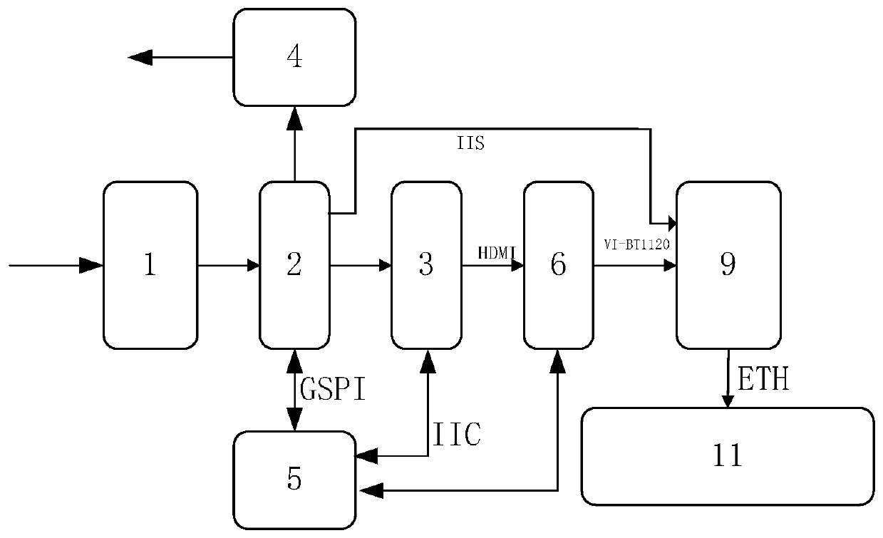
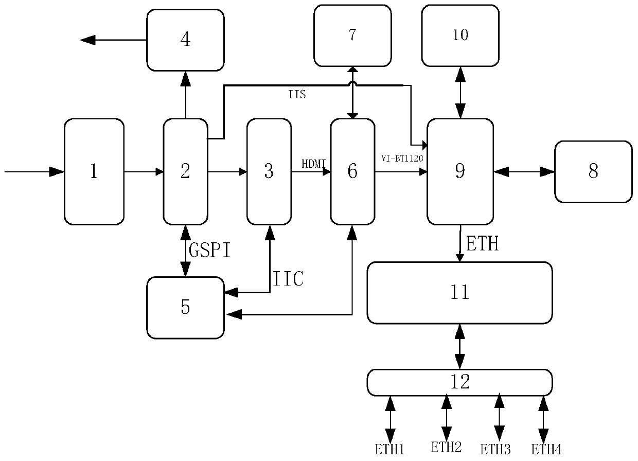
[0027] refer to figure 1 , an optical fiber signal encoder proposed by the present invention, comprising: an optical fiber signal input module 1, an SDI signal receiving module 2, an HDMI signal transmitting module 3, an SDI signal driving module 4, an HDMI signal receiving module 6, and an encoding main processor module 9 and switch module 11.

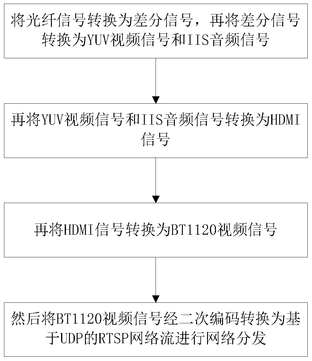
[0028] The optical fiber signal input module 1 is connected to the SDI signal receiving module 2 for converting the optical fiber signal into a differential signal and inputting it to the SDI signal receiving module 2 . In this embodiment, the optical fiber signal input module 1 uses a 3Gbps Video SFP Optical Receiver, and the 3G optical fiber receiver can receive data rates from 50Mbps to 2.97Gbps, and is compatible with SDI SMPTE259M, SMPTE 344M, SMPTE 292M and SMPTE 424M serial rates.

[0029] The SDI signal receiving module 2 is also connected to the HDMI signal sending module 3 for converting the differential signal into YUV format


PUM


Abstract

The invention provides an optical fiber signal encoder which comprises an optical fiber signal input module, an SDI signal receiving module, an HDMI signal sending module, an SDI signal driving module, an HDMI signal receiving module, an encoding main processor module and a switch module. According to the optical fiber signal encoder provided by the invention, data are transmitted through an optical fiber signal, so that a problem of video ultra-long-distance transmission is solved. An optical fiber signal is converted into an HDMI signal to be sent, and efficient compression of a video signalis completed; meanwhile, the received HDMI signal is converted into a BT1120 video signal, and then the BT1120 video signal is converted into an RTSP network flow based on UDP through secondary coding for network distribution, so that problems of real-time playing, bandwidth transmission, storage, high-definition display and the like of the video are solved.

Description


Claims


Application Information

Patent Timeline
Owner HEFEI SIWILL INTELLIGENT
Why Eureka
Try Eureka