Blood purification device

A blood purification and blood technology, which is applied in the fields of blood filtration, hypodermic injection equipment, medicine equipment, etc., can solve the problem of lack of existing technical literature information and other problems

Pending Publication Date: 2021-06-15
NIKKISO COMPANY
View PDF0 Cites 0 Cited by
  • Summary
  • Abstract
  • Description
  • Claims
  • Application Information

AI Technical Summary

Benefits of technology

This patented technology describes various technical features related to improving the performance of medical devices such as kidneydiazers used during hemodialyzer treatments. By continuously delivering new fluid through the system while keeping track of its usage throughout the procedure helps prevent errors caused by insufficient empty volumes being delivered due to lack of spare parts. Additionally, there may include other functions like priming operations where the replacement solution needs to be added beforehand, allowing for precise addition without any residual material left behind. Overall, these improvements improve the efficiency and accuracy of the reninsechanger function in hemodiafilters.

Problems solved by technology

This patented technical problem addressed in this patents relates to monitoring the amount of urine remaining within different parts of the system before and during medical procedures involving dialytic treatments like HD and HFD. Existing methods involve manual measurement of residual fluids on scales attached to the part being treated, leading to potential overfill issues due to excessive amounts of liquor entering the disposable components themselves.

Method used


Image

  • Blood purification device
  • Blood purification device
  • Blood purification device

Examples


Embodiment Construction

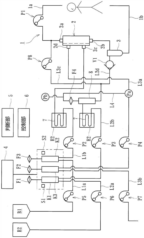
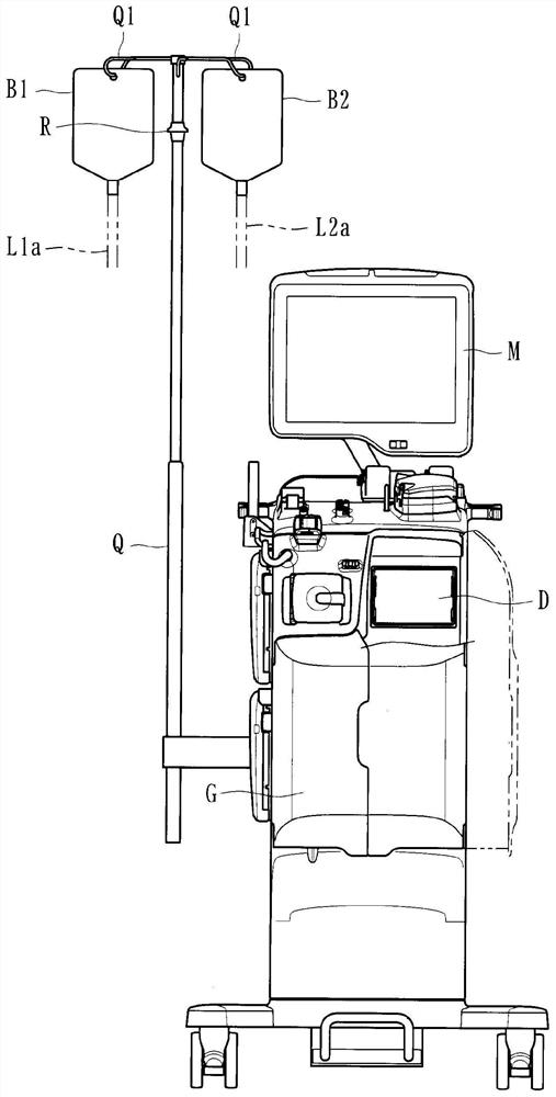
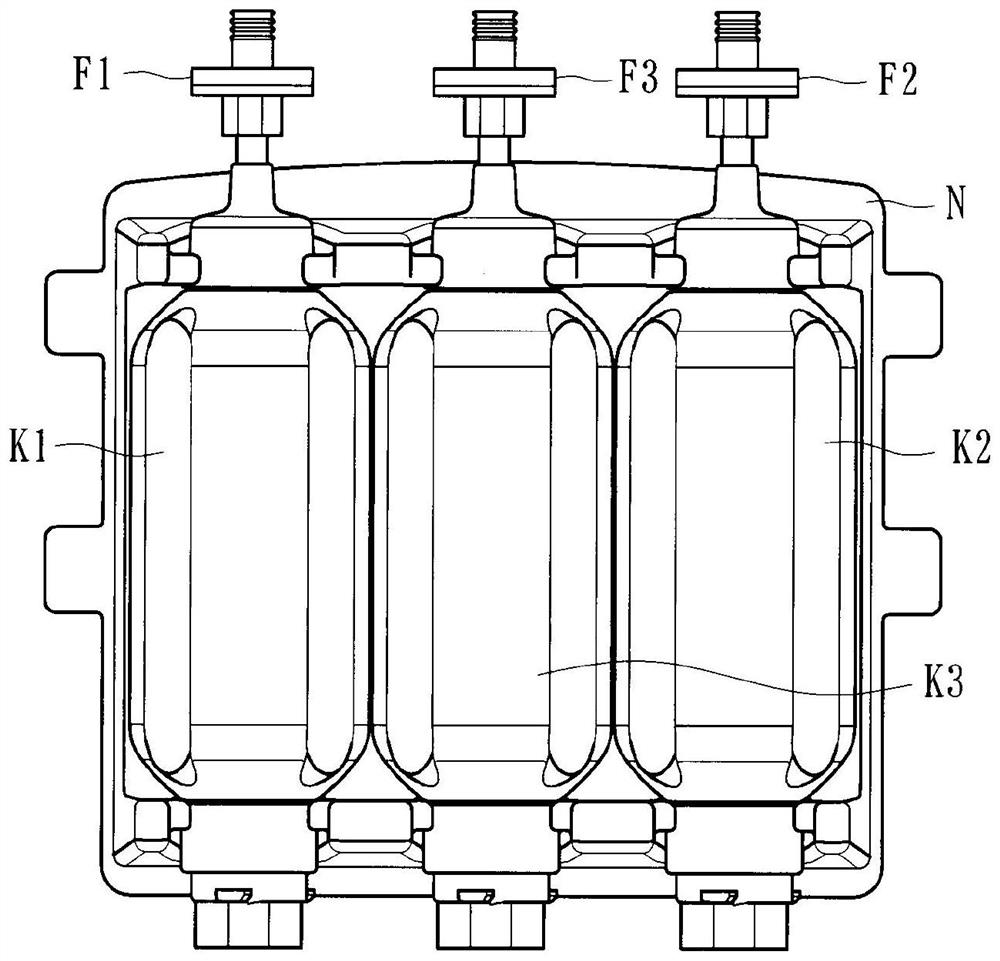
[0049] Embodiments of the present invention will be specifically described below with reference to the accompanying drawings. The blood purification device of this embodiment is suitable for a hemodialysis device for purifying blood of a patient while performing extracorporeal circulation, such as Figure 1~3 As shown, the blood circuit 1 has an arterial side blood circuit 1a and a venous side blood circuit 1b; a dialyzer 2 (blood purifier), which is sandwiched between the arterial side blood circuit 1a and the venous side blood circuit 1b Purify the blood flowing in the blood circuit 1; the first dialysate inlet line L1a and the second dialysate inlet line L1b; the first fluid replacement line L2a and the second fluid replacement line L2b; the front fluid replacement line L2c and the post fluid replacement line L2d; the first drainage discharge line L3a and the second drainage discharge line L3b; blood pump P1; dialysate introduction pump P2; first infusion pump P3; drainage dis


PUM


Abstract

The present invention relates to a blood purification device comprising a discharge liquid subdivision chamber for pooling a discharge liquid being discharged from a blood purification apparatus purifying blood of a patient, a first discharge liquid discharge line for causing the discharge liquid to flow through to the discharge liquid subdivision chamber, a second discharge liquid discharge line for causing the discharge liquid pooled by the discharge liquid subdivision chamber to be discharged to the exterior of the device, a discharge unit disposed on the second discharge liquid discharge line for discharging the discharge liquid pooled by the discharge liquid subdivision chamber to the exterior of the device, a residual amount detection unit for detecting the residual amount of the discharge liquid pooled by the discharge liquid subdivision chamber, a determination unit for determining, on the basis of the detection result from the residual amount detection unit, whether or not the discharge liquid amount in the discharge liquid subdivision chamber has reached a reference residual amount, and a control unit for controlling the discharge unit, wherein the control unit controls the discharge unit to execute a discharging step of discharging the discharge liquid pooled by discharge liquid subdivision chamber to the exterior of the device, and end the discharging step when the determination unit determines that the discharge liquid amount in the discharge liquid subdivision chamber has reached the reference residual amount.

Description


Claims


Application Information

Patent Timeline
Owner NIKKISO COMPANY
Why Eureka
Try Eureka