Pleural effusion suction device for cardiovascular surgery
A pleural effusion and cardiovascular technology, applied in the direction of suction devices, etc., can solve the problems of long suction time and difficult wound healing, and achieve the effect of prolonging the suction time and facilitating healing
- Summary
- Abstract
- Description
- Claims
- Application Information
AI Technical Summary
Problems solved by technology
Method used
Image

Examples
Embodiment 1
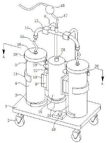
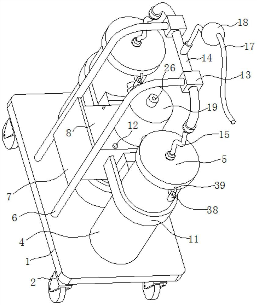
[0026] refer to Figure 1-3 , a pleural effusion suction device for cardiovascular surgery, comprising a mobile seat, a fixed frame, a container barrel 4, an end cover 5, a liquid guiding mechanism and an air bag 18, wherein:
[0027] A plurality of container barrels 4 are placed on the movable seat, the end cover 5 is clamped to the container barrel 4, the fixed frame is fixedly connected to the movable seat, the fixed frame is fixedly connected to the container barrel 4, the fixed frame is fixedly connected to the liquid guide mechanism, and the liquid guide mechanism is connected to the end cover 5, The air bag 18 is connected to the liquid guiding mechanism, and the moving seat drives the container barrel 4 to move. After moving to the corresponding position, the hand presses the air bag 18. After the external force disappears, negative pressure is generated in the liquid guiding mechanism, and the pleural effusion flows from the inlet of the liquid guiding mechanism. The eff
Embodiment 2
[0034] By pressing the airbag 18 to generate negative pressure in the catheter 17, it is necessary to continuously press the airbag 18, and the effusion also passes through the airbag 18 during the liquid suction process. The inlet is sprayed out, causing the effusion in the conduit 17 to flow back, refer to Figure 1-5 , as another preferred embodiment of the present invention, on the basis of Embodiment 1, it also includes a hollow column 19, a power mechanism, a one-way outlet valve 26, a fixed sleeve 27, a one-way inlet valve 28 and a push mechanism, and the hollow column 19 is fixedly connected to the fixed frame, the hollow column 19 is perpendicular to the movable seat, the upper end of the hollow column 19 is connected to the one-way air outlet valve 26, and the push mechanism is slidably connected in the hollow column 19, and the push mechanism is matched with the hollow column 19, and the power mechanism is fixedly connected The moving seat and the push mechanism are co
Embodiment 3
[0040] After the effusion is housed in the container barrel 4, the container barrel 4 needs to be cleaned after the operation. When the container barrel 4 is cleaned, water or effusion will enter the push plate 25 and the one-way air outlet Between the valves 26, adhere to the inner wall of the hollow column 19, thereby affecting the movement of the push plate 25, refer to Figure 1-5 , as another preferred embodiment of the present invention, on the basis of Embodiment 2, it also includes a fixed box 29, an elastic sealing mechanism, a connecting pipe 35, a connecting sleeve 38 and a limit rod 39, and the fixed box 29 communicates with the one-way air intake The valve 28 and the fixed box 29 are used to prevent water or effusion from passing through the one-way inlet valve 28. The upper end of the fixed box 29 is provided with a first air guide hole 34, and one end of the connecting pipe 35 is fixedly connected to the end cap 5, and the connecting pipe 35 The other end passes th
PUM
 Abstract
Description
Claims
Application Information
 - R&D Engineer
- R&D Manager
- IP Professional
- Industry Leading Data Capabilities
- Powerful AI technology
- Patent DNA Extraction
Browse by: Latest US Patents, China's latest patents, Technical Efficacy Thesaurus, Application Domain, Technology Topic.
© 2024 PatSnap. All rights reserved.Legal|Privacy policy|Modern Slavery Act Transparency Statement|Sitemap