Isolating switch of on-load tap-changer

A technology of on-load tap changer and isolating switch, applied in electric switches, air switch parts, high-voltage/high-current switches, etc., can solve the problems of large sliding friction, affecting the service life of switches, etc. Ensure stable and tight contact and reliable electrical characteristics

Pending Publication Date: 2021-12-03
CHINA ELECTRIC POWER RES INST +1
View PDF0 Cites 0 Cited by
  • Summary
  • Abstract
  • Description
  • Claims
  • Application Information

AI Technical Summary

Problems solved by technology

[0004] In view of this, the present invention proposes a disconnector for an on-load tap changer, aiming to solve the problem th

Method used


Image

  • Isolating switch of on-load tap-changer
  • Isolating switch of on-load tap-changer
  • Isolating switch of on-load tap-changer

Examples


Example Embodiment

[0023] An exemplary embodiment of the present disclosure will be described in more detail below with reference to the accompanying drawings. Although the exemplary embodiments of the present disclosure are shown, it is understood that the disclosure can be implemented in various forms without limitation. Instead, these embodiments are provided to be more thoroughly understood to disclose the present disclosure, and can communicate the scope of the scope of the present disclosure to those skilled in the art. It should be noted that the features of the present invention in the present invention may be combined with each other in the case of an unable conflict. The present invention will be described in detail below with reference to the accompanying drawings.

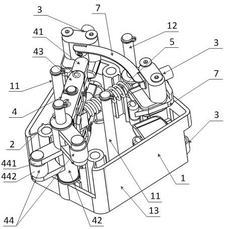
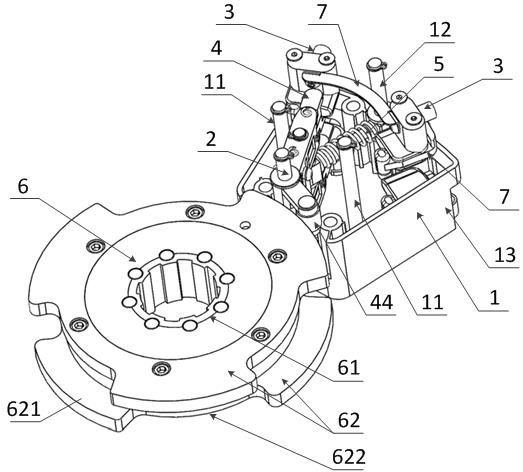
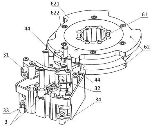
[0024] See Figure 1 to 3 It shows a preferred structure of the isolation switch of the present invention provided by the embodiment of the present invention. As shown, the separation switch comprises: switch housing 1, a cutting


PUM


Abstract

The invention provides an isolating switch of an on-load tap-changer. The isolating switch comprises: a switch shell; a shifting fork rotating shaft arranged in the switch shell; four static contacts; a switch shifting fork, wherein one end of the switch shifting fork is rotatably arranged on the shifting fork rotating shaft, and the other end of the switch shifting fork is provided with a moving contact; and a dead point spring, wherein the first end of the dead point spring is connected with the switch shell, and the second end of the dead point spring is connected with the switch shifting fork. Parts of parts of the isolating switch are loaded through the switch shell, so that the isolating switch serves as an integral switch structure and serves as an independent component to be installed and designed; the switch shifting fork is rotatably connected to the shifting fork rotating shaft, so that the switch shifting fork swings and drives the moving contact to be in switching contact with the two columns of static contacts, and the transition on-off time sequence of the vacuum envelope is controlled; and meanwhile, the dead point position of the dead point spring is arranged between two static positions where the moving contact is contacted with the two columns of static contacts, so that stable and compact contact between the moving contact and the two columns of static contacts is ensured, and the electrical characteristic is reliable.

Description


Claims


Application Information

Patent Timeline
Owner CHINA ELECTRIC POWER RES INST
Why Eureka
Try Eureka