Cable bridge corner branching device

A branching device, cable tray technology, applied in the direction of electrical components, etc., can solve the problem of single function, etc., to achieve the effect of ingenious conception, convenient assembly and disassembly, and reasonable structure setting

Inactive Publication Date: 2021-12-24
深圳市中深通电缆桥架有限公司
View PDF0 Cites 0 Cited by
  • Summary
  • Abstract
  • Description
  • Claims
  • Application Information

AI Technical Summary

Problems solved by technology

[0004] The purpose of the present invention is to provide a cable tray corner branching device, which aims to solve the problem that the cable tray in the prior art needs to be c

Method used


Image

  • Cable bridge corner branching device
  • Cable bridge corner branching device
  • Cable bridge corner branching device

Examples


Embodiment

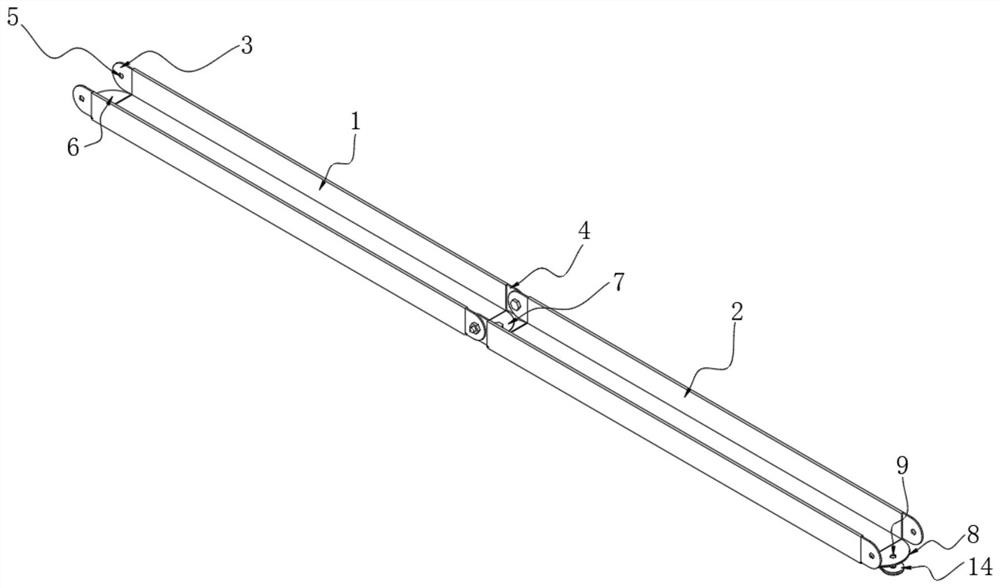
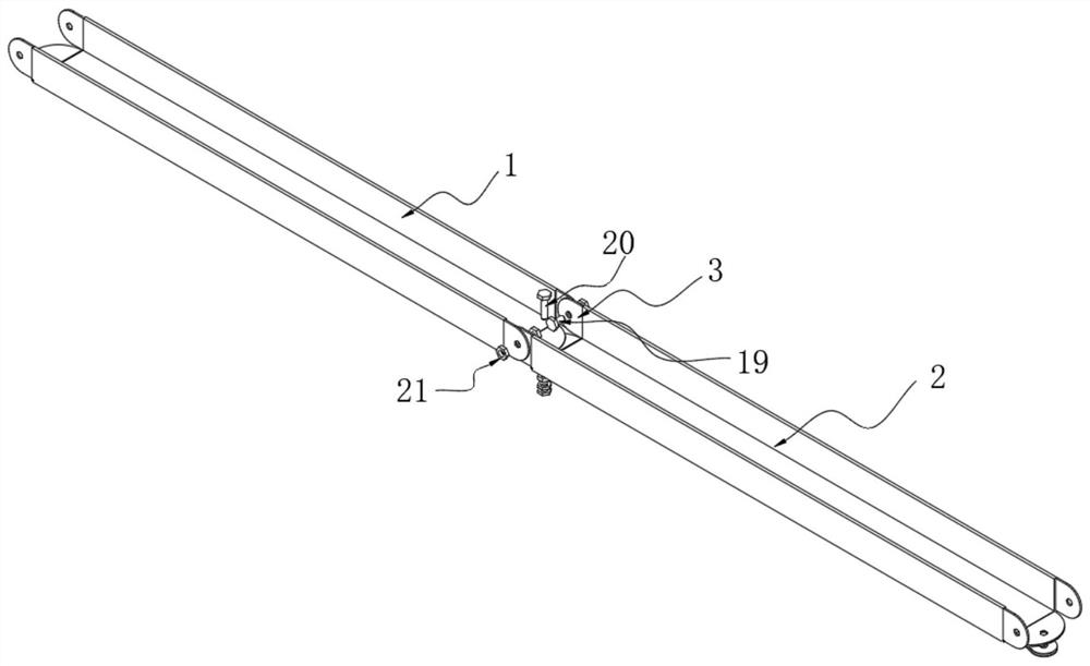
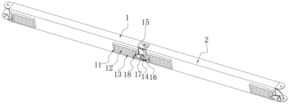
[0032] see Figure 1-Figure 9 , the present invention provides the following technical solutions: a cable tray corner branching device includes a first bridge 1 and a second bridge 2, the first bridge 1 and the second bridge 2 are connected end to end, and the first bridge 1 and the second bridge 2 The structure is the same, the left and right side walls of the first bridge frame 1 are respectively provided with an insert plate 6 and a connecting plate 7, and a card slot 8 is opened in the connecting plate 7, and the card slot 8 is movably inserted with the insert plate 6, and the insert plate 6 and the Threaded holes 9 are provided on the connecting plate 7, two connecting plates 3 and inserting plates 4 are respectively fixed on the left and right side walls of the first bridge frame 1, and mounting holes 5 are provided on the two connecting plates 3 and inserting plates 4, The left and right sides of the bottom of the first bridge frame 1 are all fixed with bottom plates 11, a


PUM


Abstract

The invention provides a cable bridge corner branching device, which belongs to the technical field of cable bridges. The cable bridge corner branching device comprises a first bridge and a second bridge, the first bridge and the second bridge are connected end to end, the structures of the first bridge and the second bridge are the same, the left and right side walls of the first bridge are respectively provided with an insertion disc and a connection disc, a clamping groove is formed in the connection disc, the clamping groove is movably connected with the insertion disc in an inserted mode, threaded holes are formed in the insertion disc and the connection disc, two connection plates and an insertion plate are fixed to the left side wall and the right side wall of the first bridge correspondingly, mounting holes are formed in the two connection plates and the insertion plate correspondingly, and bottom plates are fixed to the left side and the right side of the bottom of the first bridge correspondingly. The whole device has a reasonable structure, the thinking is delicate, assembly and disassembly are convenient, the connection is firm, a transverse corner and a vertical corner between two bridges are supported, the device can adapt to installation conditions of different steering directions, and is convenient to process and transport due to the fact that the bridge single bodies are the same in structure, thereby being high in practicability.

Description


Claims


Application Information

Patent Timeline
Owner 深圳市中深通电缆桥架有限公司
Why Eureka
Try Eureka