Method and device for determining collision risk of unmanned aerial vehicle

A collision risk and UAV technology, applied in the computer field, can solve problems such as low efficiency and large amount of calculation for identifying UAVs, and achieve the effect of improving efficiency

Active Publication Date: 2022-01-21
浙江这里飞科技有限公司
View PDF12 Cites 5 Cited by
  • Summary
  • Abstract
  • Description
  • Claims
  • Application Information

AI Technical Summary

Benefits of technology

This patented technology helps prevent collisions between drones that may be flying near each other without any human intervention. It involves collecting data on both their own position (latitudes) and its surroundings from different sources like GPS signals or radar measurements. These techniques help calculate how far they can collide - based upon factors such as distance travelled over time. They also use this knowledge about space around them to create maps showing which areas have been hit during flight. Overall, these technologies improve the accuracy and speed of detecting potential collisations.

Problems solved by technology

The technical problem addressed by this patented method for predicting potential collisions with other aircraft during take off or landing on an airport has been that current methods require significant computational resources due to high altitude data collection requirements. This makes them difficult if there were many more dronies being taken down at once without any warnings about their future movements.

Method used


Image

  • Method and device for determining collision risk of unmanned aerial vehicle
  • Method and device for determining collision risk of unmanned aerial vehicle
  • Method and device for determining collision risk of unmanned aerial vehicle

Examples


Embodiment 1

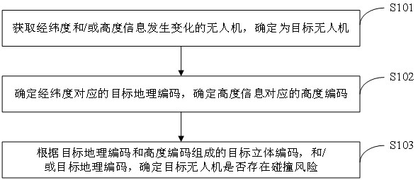
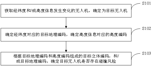
[0063] Embodiment 1: Determine whether the target UAV has a collision risk according to the target stereo code composed of the target geographic code and the altitude code.

[0064] see Figure 5 , Figure 5 It is a schematic diagram of target stereo encoding in the embodiment of this application. That is to say, in the flying airspace, the target UAV is located in Figure 5 The spatial region corresponding to the target stereo code wtmk4rbp001110 is shown.

[0065] see image 3 , image 3 It is a flow chart of determining whether the target UAV has a collision risk according to the target stereo code composed of the target geographic code and the altitude code provided by the embodiment of the present application. Such as image 3 As shown, the embodiment of the present application provides a target stereo code composed of a target geographic code and an altitude code to determine whether the target UAV has a collision risk, including the following steps:

[0066] S10311.

Embodiment 2

[0072] Embodiment 2: According to the geographic code of the target, it is determined whether the target UAV has a collision risk.

[0073] see Figure 4 , Figure 4 It is a flow chart of determining whether a target UAV has a collision risk according to the target geocode provided by the embodiment of the present application. Such as Figure 4 As shown, the determination of whether the target UAV has a collision risk according to the target geocoding provided by the embodiment of the present application includes the following steps:

[0074] S10321. Obtain geocodes adjacent to the target geocode.

[0075] Wherein, the geocodes adjacent to the target geocode refer to the geocodes of the grids adjacent to the grid corresponding to the target geocode.

[0076] The adjacent geocoding in the embodiment of the present application refers to creating a nine-square grid with the target geocode as the center, and the remaining eight geocodes of the nine-square grid except the central


PUM


Abstract

The invention provides a method and device for determining the collision risk of an unmanned aerial vehicle, and the method comprises the steps: obtaining an unmanned aerial vehicle with the longitude and latitude and/or height information changing, and determining the unmanned aerial vehicle as a target unmanned aerial vehicle; determining a target geocode corresponding to the longitude and latitude, and determining a height code corresponding to the height information, the target geocode being used for uniquely identifying the plane area range of the target unmanned aerial vehicle, and the height code being used for uniquely identifying the height range of the target unmanned aerial vehicle; and determining whether the target unmanned aerial vehicle has a collision risk or not according to a target stereo code composed of the target geocode and the height code and/or the target geocode. By comparing the stereo code or the geocode of the unmanned aerial vehicle, the technical problems of large calculation amount and low efficiency of identifying whether the unmanned aerial vehicle has the collision risk are solved, and the technical effect of improving the efficiency of identifying whether the unmanned aerial vehicle has the collision risk is achieved.

Description


Claims


Application Information

Patent Timeline
Owner 浙江这里飞科技有限公司
Why Eureka
Try Eureka