Lamp body structure and lamp

A lamp body and lamp technology, which is applied to lighting devices, lighting device parts, light source fixing, etc.

Pending Publication Date: 2022-02-01
BEIJING SMARTMI TECH
View PDF4 Cites 0 Cited by
  • Summary
  • Abstract
  • Description
  • Claims
  • Application Information

AI Technical Summary

Benefits of technology

The technology described in this patented design allows for easier control over how light from an illuminated bulb travels through different parts of its casing. This makes it simpler than traditional methods that require multiple components or tools like lamps with reflective surfaces attached thereto.

Problems solved by technology

The technical problem addressed in this patented text relates how to achieve both improved illumination effects for tables/lamp lights while also having good ornamental features like columns with an optical system.

Method used


Image

  • Lamp body structure and lamp
  • Lamp body structure and lamp

Examples


Embodiment Construction

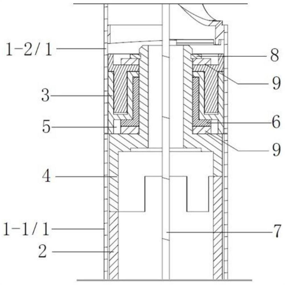
[0021] In the embodiment of the present invention, the lamp body can be rotated in multiple stages. When it is necessary to adjust the light output direction, it is enough to rotate the corresponding sub-housing without rotating the base, which will be described in detail below.

[0022] figure 1 It is a cross-sectional view of the rotating device in the lamp body structure provided by the embodiment of the present invention. Such as figure 1 As shown, the lamp body structure includes: a cylindrical housing and a rotating device; the cylindrical housing includes a plurality of superimposed sub-housings 1, and adjacent sub-housings 1 are connected by a rotating device; the rotating device includes a first rotating Part 2 and the second rotating part 3, the adjacent sub-housing 1 includes the first sub-housing 1-1 and the second sub-housing 1-2, the first rotating part 2 is fixed on the first sub-housing 1- 1, the second rotating part 3 is fixed in the second sub-housing 1-2; the


PUM


Abstract

The invention relates to the technical field of lighting equipment, in particular to a lamp body structure and a lamp. The lamp body structure comprises a columnar shell and a rotating device; the columnar shell comprises a plurality of sub-shells which are arranged in an overlapped mode, and every two adjacent sub-shells are connected through a rotating device; the rotating device comprises a first rotating part and a second rotating part, the adjacent sub-shells comprise a first sub-shell and a second sub-shell, the first rotating part is fixedly arranged in the first sub-shell, and the second rotating part is fixedly arranged in the second sub-shell; and the first rotating part is provided with a rotating shaft extending in the direction of the second rotating part, the second rotating part is provided with a shaft hole, and the rotating shaft is arranged in the shaft hole in a penetrating mode and can rotate in the shaft hole in the circumferential direction. According to the technical scheme, the adjacent sub-shells are connected through the rotating device, then the two sub-shells can rotate relatively, and when the angle of the light outlet needs to be adjusted, only the sub-shells need to be rotated. When the direction of the lamp body structure is adjusted, the lamp body does not need to be adjusted integrally, and direction adjusting operation is simpler and faster.

Description


Claims


Application Information

Patent Timeline
Owner BEIJING SMARTMI TECH
Why Eureka
Try Eureka