Advertisement lighting device

Inactive Publication Date: 2005-11-24
NODA ELECTRIC IND
View PDF6 Cites 0 Cited by
  • Summary
  • Abstract
  • Description
  • Claims
  • Application Information

AI Technical Summary

Benefits of technology

[0008] In view of the foregoing disadvantages, it is an object of the invention to provide an advertisement lighting device for decreasing deviation to the middle of fluorescent lamp of radiation of the fluresce

Problems solved by technology

As space between the light sources is larger, uneven light materializes on the diffusing plate.
However, if space between the two fluorescent lamps 104 decrea

Method used


Image

  • Advertisement lighting device
  • Advertisement lighting device
  • Advertisement lighting device

Examples


Embodiment Construction

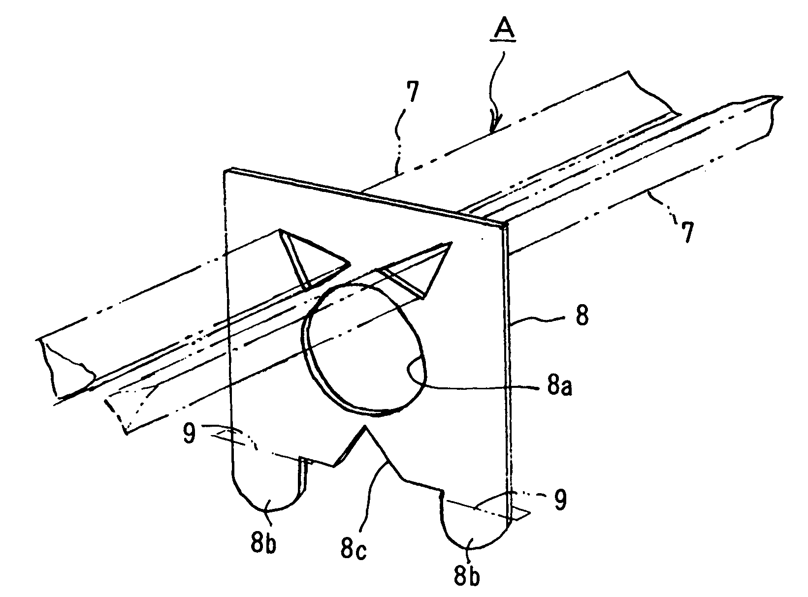
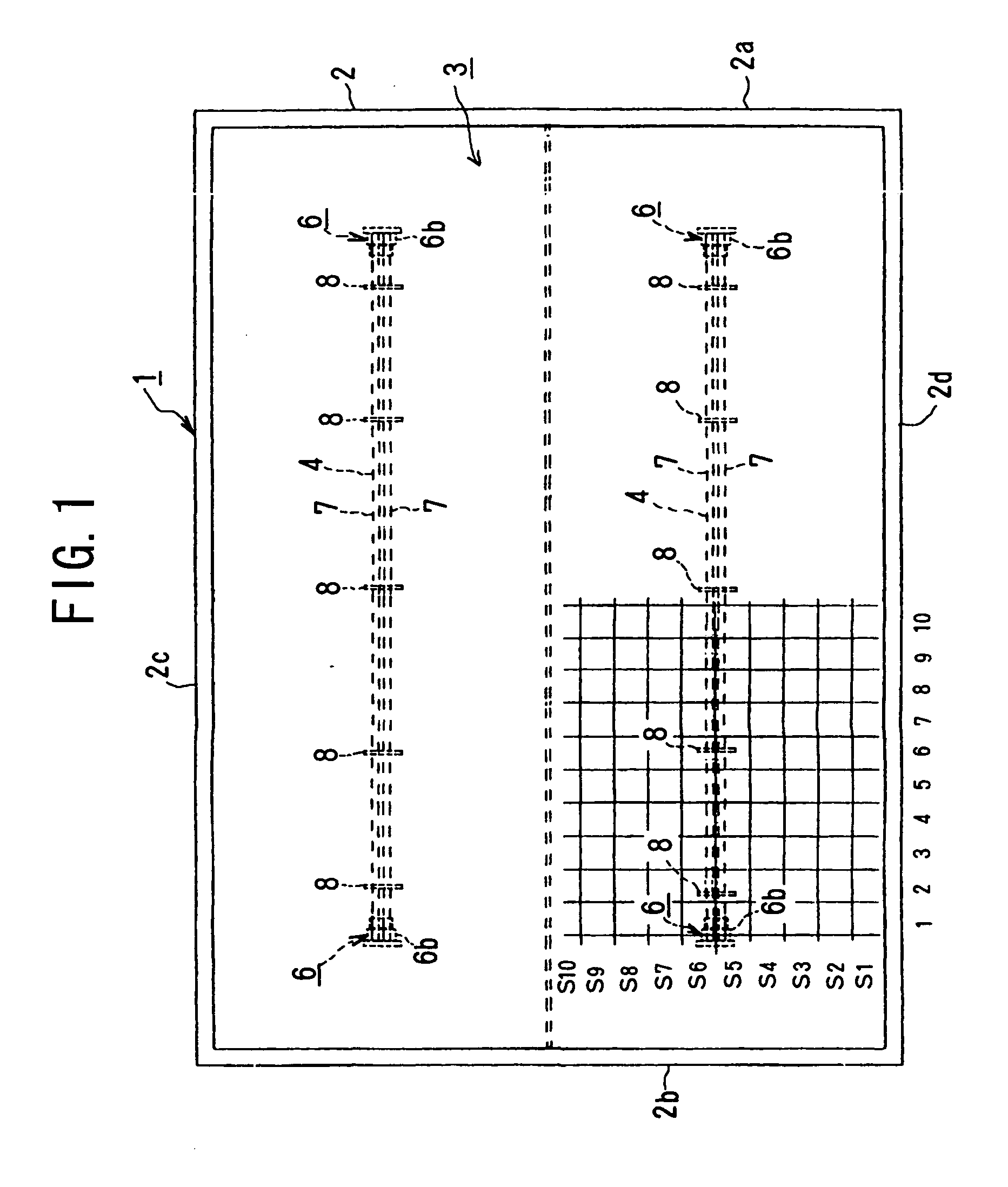
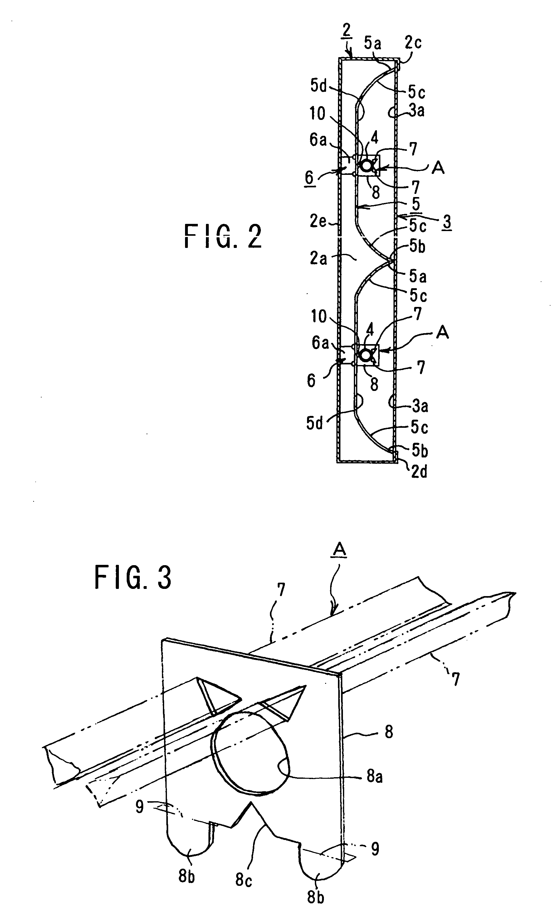
[0022] In an advertisement lighting device 1 as shown in FIGS. 1 and 2, a diffusing plate 3 is provided in the front of a casing 2, and behind the diffusing plate 3, one or more horizontal straight-tube light sources such as two horizontal fluorescent lamps 4 are provided in parallel with a radiated surface 3a of the diffusing plate 3. Behind each of the fluorescent lamps 4, a reflecting plate 5 is provided respectively.

[0023] The right and left ends of the reflecting plate 4 contact a right frame member 2a and a left frame member 2b. Each of the fluorescent lamps 4 is provided in the middle of upper and lower halves respectively. The upper end 5a of the upper reflecting plate 5 and lower end 5b of the lower reflecting plate 5 contacts an upper frame member 2c and a lower frame member 2d of the casing 2 respectively.

[0024] The upper and lower reflecting plates 5 are connected to each other by connecting the lower end 5b of the upper reflecting plate 5 to the upper end 5a of the lower


PUM


Abstract

An advertisement lighting device has a fluorescent lamp in a casing. In front of and closer to the fluorescent lamp, a prism is provided to disperse light radiated from the fluorescent lamp. A reflecting plate is formed on the back of the casing to reflect light radiated directly from the fluorescent lamp and light dispersed through the prism to achieve uniform luminous intensity.

Description


Claims


Application Information

Patent Timeline
Owner NODA ELECTRIC IND
Why Eureka
Try Eureka