Method for measuring loss of large-scale double-reflector antenna

A dual-reflector, antenna loss technology, applied to the antenna radiation pattern and other directions, can solve problems such as large measurement errors, and achieve the effects of suppressing influence, promoting and applying value, and high measurement accuracy

Pending Publication Date: 2022-08-09
NO 54 INST OF CHINA ELECTRONICS SCI & TECH GRP
View PDF0 Cites 0 Cited by
  • Summary
  • Abstract
  • Description
  • Claims
  • Application Information

AI Technical Summary

Benefits of technology

In this patented technology, two methods are used: 1) measuring lost or distorted signals from an object that needs precise measurements (such as radar), 2) by utilizing both types of radiation simultaneously - either through different devices like GPS systems or satellite communication equipment, which helps reduce interference caused by reflected waves at longer distances.

Problems solved by technology

Technological Problem addressed in this patented technical problem relates to accurate determination of lost or damaged radios for use with satellites communications systems due to factors such as environmental conditions like rainwater impacts during flight operations. Current methods involve approximative calculations based upon reflection surfaces' properties without accounting for these influences from other sources.

Method used


Image

  • Method for measuring loss of large-scale double-reflector antenna
  • Method for measuring loss of large-scale double-reflector antenna
  • Method for measuring loss of large-scale double-reflector antenna

Examples


Embodiment Construction

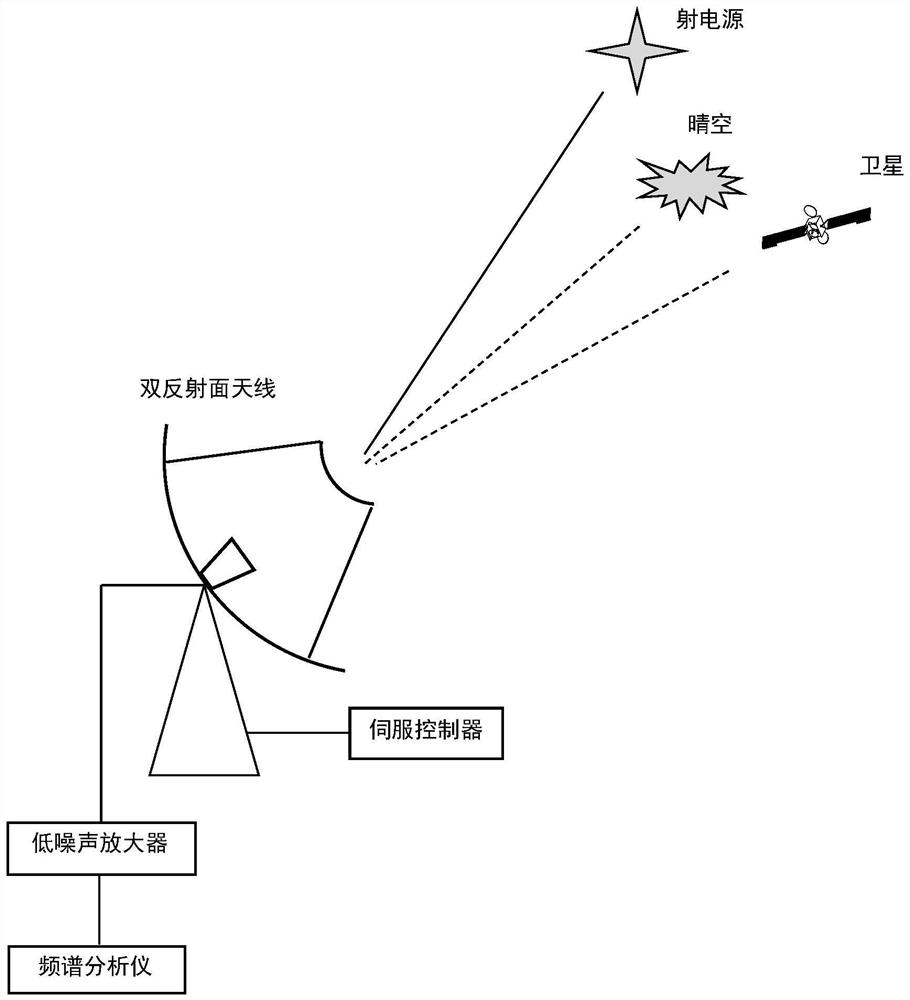
[0049] A method of measuring the loss of a large dual reflector antenna, comprising the following steps:

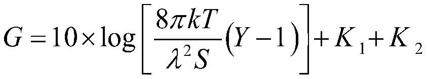
[0050] (1) Measure the power gain of the antenna. By measuring the Y factor of the ratio of the noise power of the large double-reflector antenna to the radio source and its nearby clear sky, the power gain of the antenna is calculated using the following formula.

[0051]

[0052] where:

[0053] G—the power gain of the antenna, dBi;

[0054] k—Boltzmann constant, k=1.38×10 -23 J / K;

[0055] T—Antenna system noise temperature, K;

[0056] λ—working wavelength, m;

[0057] S—the flux density of the radio source, Wm -2 Hz -1 ;

[0058] Y - the measured Y factor;

[0059] K 1 - Atmospheric attenuation correction factor, dB;

[0060] K 2 - Beam widening correction factor, dB.

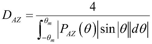
[0061] (2) Measured antenna directivity gain. Using satellite beacons, measure the azimuth power pattern and elevation power pattern of the antenna, and use P for the azimuth power pat


PUM


Abstract

The invention discloses a method for measuring loss of a large-scale double-reflector antenna. The method comprises the following steps: firstly, measuring the power gain of the large-scale double-reflector antenna by using a radio power source method; then measuring antenna orientation and pitching power directional diagrams in a limited angular domain by using a beacon of a geosynchronous orbit stationary satellite, and calculating directional gain of the antenna by using a numerical integration method; and finally, calculating the loss of the large-scale double-reflector antenna according to the measured antenna power gain and directional gain and considering antenna irradiation loss correction, support shielding correction, axial cross polarization loss correction and mismatch correction. The method is simple and feasible, and has popularization and application values.

Description


Claims


Application Information

Patent Timeline
Owner NO 54 INST OF CHINA ELECTRONICS SCI & TECH GRP
Why Eureka
Try Eureka