Ink jet printer for the labelling of goods with a write head and a supply tank

a technology of supply tank and write head, which is applied in the field ofink jet printers, can solve the problems of defective supply of compressed air, short supply of ink, and inability to detect defective ink pressure, and achieve the effects of reducing pressure in the ink line, erroneously displayed values, and air pressure energy

Active Publication Date: 2020-01-07
EBS INK JET SYST
View PDF8 Cites 0 Cited by
  • Summary
  • Abstract
  • Description
  • Claims
  • Application Information

AI Technical Summary

Benefits of technology

This patent describes an ink system with a pneumatically driven pump that generates pressure on an ink tank. When enough ink is present, the pump starts sending pressure towards the ink tank. However, if too much ink is left behind or some other problem occurs, the pump stops sending pressure back into the tank. By measuring this pressure difference before shutting off, any issues like poor printing quality caused by insufficient ink supply are identified early. Additionally, monitoring the air pressure at different locations helps prevent problems like overfeeding or underfilling the printer's ink tanks.

Problems solved by technology

This patent describes various technical problem addressed in the patent text: The current design of inkjet printers has issues with maintaining sufficient liquid level within the supply tank due to frequent replacement of the empty container containing the fluid. Additionally, the use of external power sources can lead to instability during printing procedures.

Method used


Image

  • Ink jet printer for the labelling of goods with a write head and a supply tank
  • Ink jet printer for the labelling of goods with a write head and a supply tank
  • Ink jet printer for the labelling of goods with a write head and a supply tank

Examples


Embodiment Construction

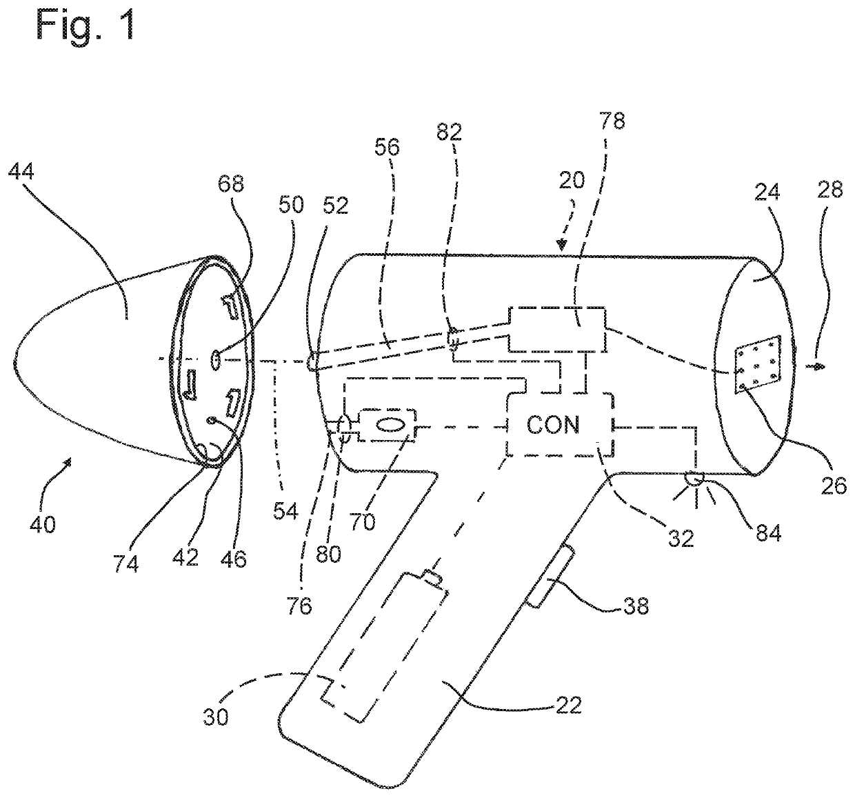
[0024]According to the two working examples, the ink jet printer for the labelling of goods is designed as a hand-held device. It comprises a main unit 20, which herein essentially is cylindrically formed having an attached handle 22. In FIG. 1, a frontal surface 24 is located at the right hand side of the main unit 20, where several ink 49 outlet openings 26 are provided. Discharge of ink is according to the arrow 28. Printing is preferably done with ink droplets. In the handle 22, a voltage supply 30 is accommodated, as represented as an accumulator. It is connected with a controller CON 32, which controls the overall operational procedure. In the handle 22, a release button 38 is mounted, through which a pressurizing procedure will be initiated.

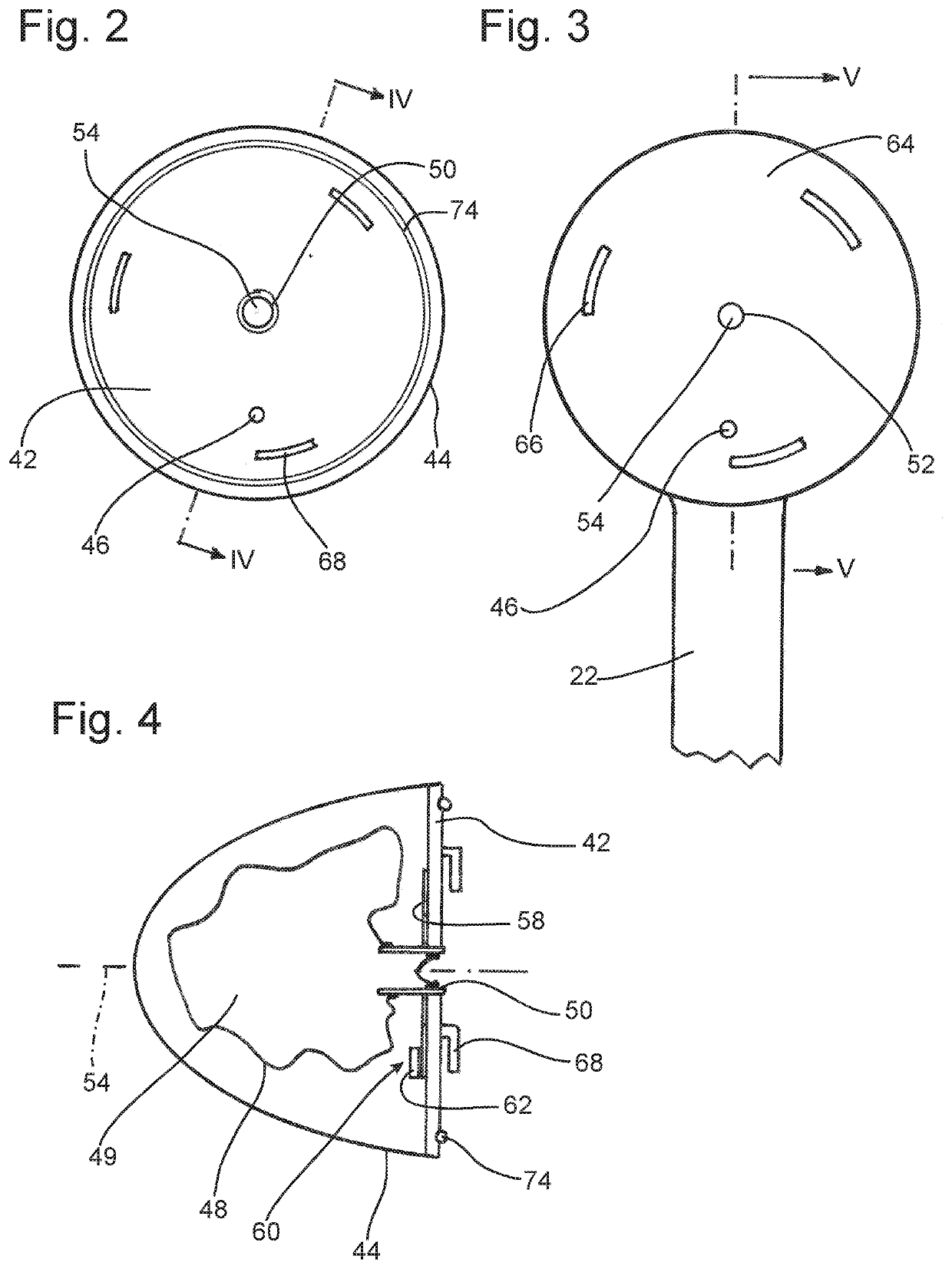
[0025]In FIG. 1, on the left hand side adjacent to the main unit 20 a supply tank 40 is located, separated by a parting plane. It has its own housing. It is limited by a planar container wall 42, which has the shape of a disc, and by an air-t


PUM


Abstract

The ink jet printer for the labelling of goods has a write head, which comprises at least one outlet opening for ink droplets, a printing mechanism connected to said outlet opening, a pneumatic pump and an electrical control. It has at least one supply tank for fluid flowing through the outlet opening. The supply tank is releasably connected to the write head in a coupling area. In the write head, a first pressure sensor is arranged at the compressed-air line, which detects the air pressure in the compressed-air line and outputs an air pressure signal to the controller. A second pressure sensor is arranged at the ink line, which detects the pressure in the ink line and outputs an ink pressure signal to the controller. Said controller outputs a signal “ink empty”, if the ink pressure signal declines by more than 10% in relation to the air pressure signal.

Description


Claims


Application Information

Patent Timeline
Owner EBS INK JET SYST
Why Eureka
Try Eureka