Antenna steering method and apparatus for an 802.11 station

Inactive Publication Date: 2005-02-17
IPR LICENSING INC
View PDF26 Cites 49 Cited by
  • Summary
  • Abstract
  • Description
  • Claims
  • Application Information

AI Technical Summary

Benefits of technology

[0006] Improvement over simple diversity is provided through a Medium Access Control (MAC) layer antenna steering process for a directional antenna used on the station side of an 802.11 wireless network. The directional antenna provides an improved signal quality in most cases allowing the link to operate at higher data rates.

Problems solved by technology

Monopole antennas are susceptible to effects that degrade the quality of communication between the station and the access points, such as reflection or diffraction of radio wave signals the station and the access points, such as reflection or diffraction of radio wave signals caused by intervening objects, such as walls, desks, people, etc.

Method used


Image

  • Antenna steering method and apparatus for an 802.11 station
  • Antenna steering method and apparatus for an 802.11 station
  • Antenna steering method and apparatus for an 802.11 station

Examples


Example

[0022] A description of preferred embodiments of the invention follows.

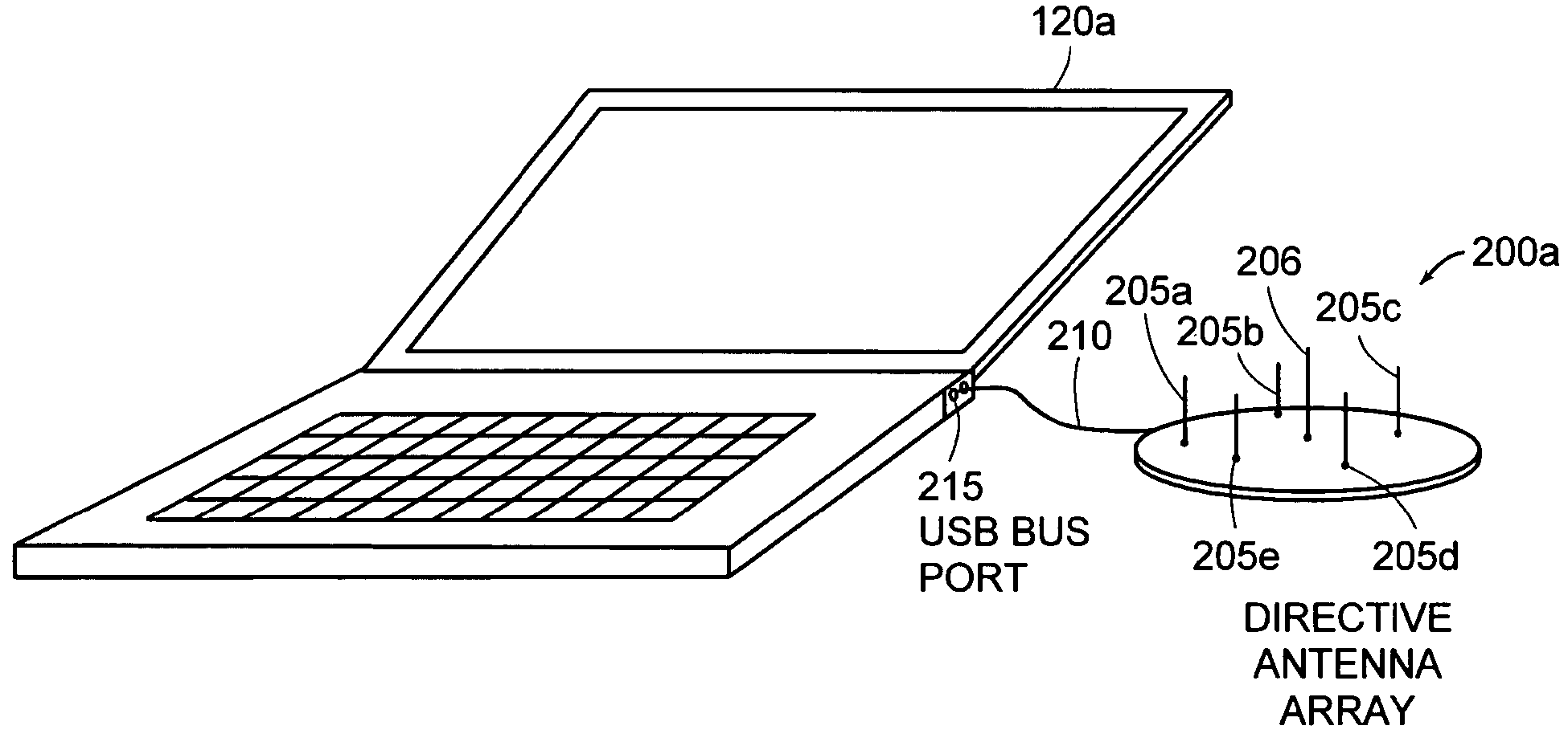
[0023] Directional antennas have traditionally been employed to improve signal quality over line-of-sight RF communications links. The directional antenna uses some form of beam-forming to increase the antenna gain in a particular direction for transmission and reception. The direction may be adjusted or chosen to improve signal quality. In application to the 802.11 wireless access media, the directional antenna provides gain as well as interference rejection and angular diversity. The present invention provides a method to determine the best pointing angle of a directional antenna within the 802.11 MAC layer protocols.

[0024] The ability of a directional antenna to provide an increase in signal quality, i.e., Signal-to-Noise Ratio (SNR), is statistical in nature. In some multi-path environments, a directional antenna may provide more than 5 dB of gain, and in others, it may not be better than an omni-directional (


PUM


Abstract

A method or apparatus steers a directional antenna for a station to communicate with an Access Point (AP) in an 802.11 protocol system. The method or apparatus may include setting the directional antenna in an omni-directional pattern during a Beacon scan. After authentication with a selected AP, the method or apparatus conducts an antenna beam selection process to determine a “best” direction for communicating with the selected AP based on a metric, such as Signal-to-Noise Ratio (SNR), of the Beacon frames received on each of the directional antenna scan angles. The method or apparatus may be integrated into or associated with a Medium Access Control (MAC) layer and receive signal quality metrics from the Physical (PHY) layer.

Description


Claims


Application Information

Patent Timeline
Owner IPR LICENSING INC
Why Eureka
Try Eureka