Counterpulsation device using noncompressed air

Inactive Publication Date: 2005-06-23
CPCA2000
View PDF26 Cites 3 Cited by
  • Summary
  • Abstract
  • Description
  • Claims
  • Application Information

AI Technical Summary

Benefits of technology

[0012] In an alternative application, the cylinder draws from a reservoir of specific gas or liquid with special characteristics that permit more thorough and rapid volume/pressure changes within the cuffs.
[0013] In still another embodiment, a multi-wave, non-distensible unit encases the entire lower hemi-

Problems solved by technology

Compressed air is disadvantageous because it must be carefully managed or it introduces potential problems.
Systems using compressed air can become overly pressurized because of a malfunction or blockage in the compressor or an associated accumulator.
Under extreme circumstances, excess pressure buildup introduces the possibility of having a portion of the system, such as a hose or the compressor housing, rupture unexpectedly.
Typical compressors also render conventional systems undesirably noisy, which makes them less than ideal for a hospital or clinic setting.
The compressors and reservoirs are also relatively large and cumbersome, which decreases their ability to be readily relocated.
The compressed air systems also require components such as vacuum pumps, which introduce additional cost, noise, complexity, an

Method used


Image

  • Counterpulsation device using noncompressed air
  • Counterpulsation device using noncompressed air
  • Counterpulsation device using noncompressed air

Examples


Embodiment Construction

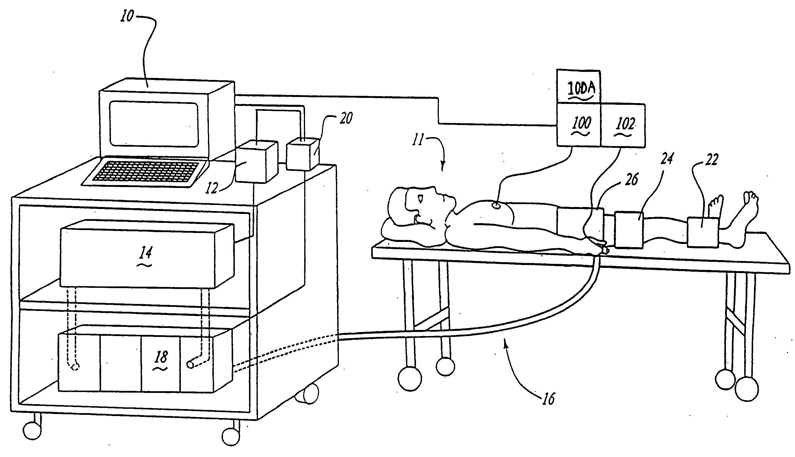
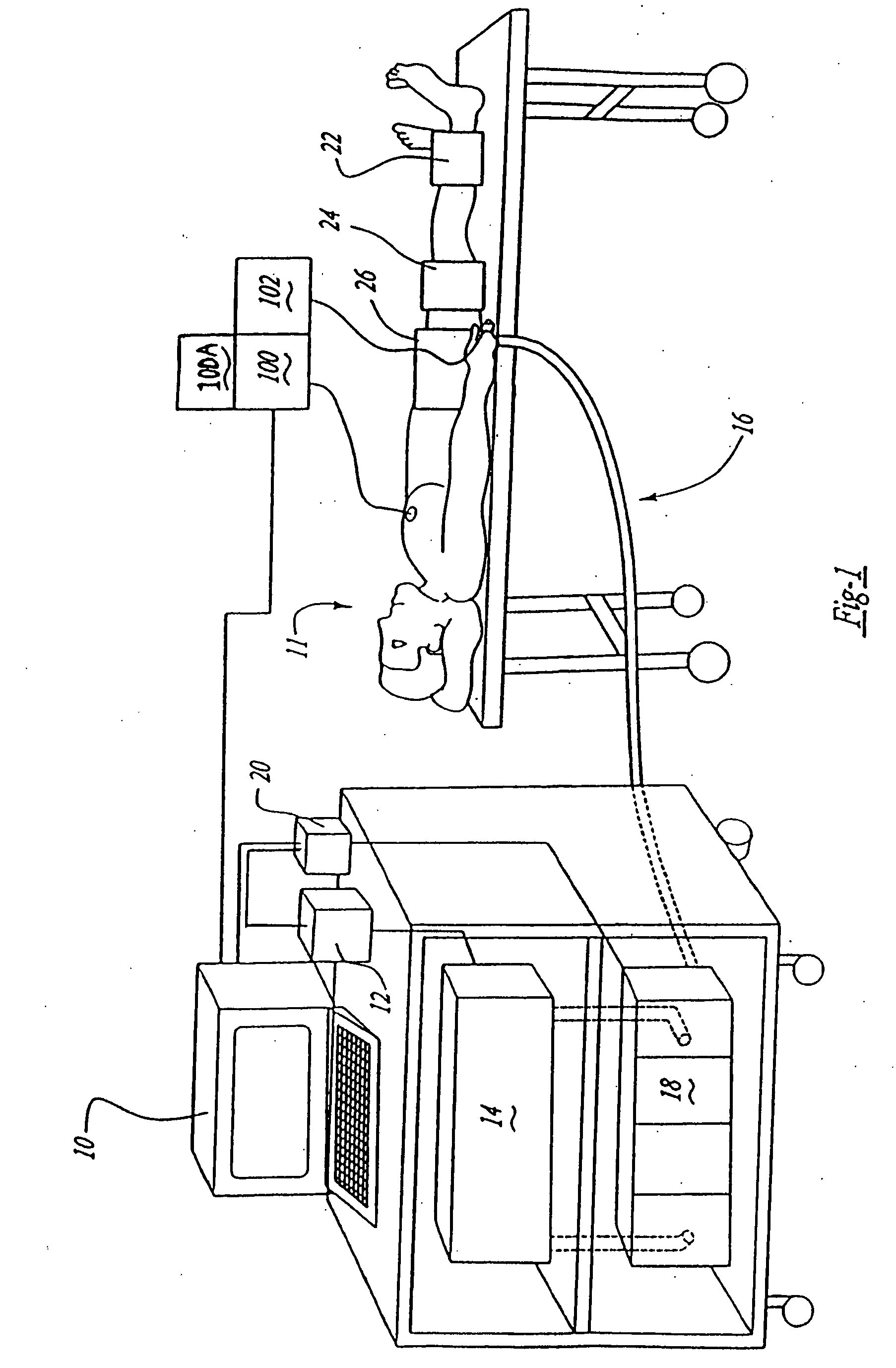
[0023]FIG. 1 diagrammatically illustrates, in simplified form, a counterpulsation system including a computer terminal 10 that enables a doctor or other health professional to operate the counterpulsation system to administer a desired therapy. regimen to a patient 11. The computer 10 communicates with a controller 20 that communicates with a second controller 12, which controls the operation of an air moving device 14. A series of conduits 16 and valves 18 are controlled by the controller 20. A plurality of inflatable cuffs 22, 24 and 26 are inflated and deflated as the air moving device 14 moves air through the conduits 16 and valves 18 to the cuffs. Only one conduit 16 is shown in FIG. 1 for simplicity.

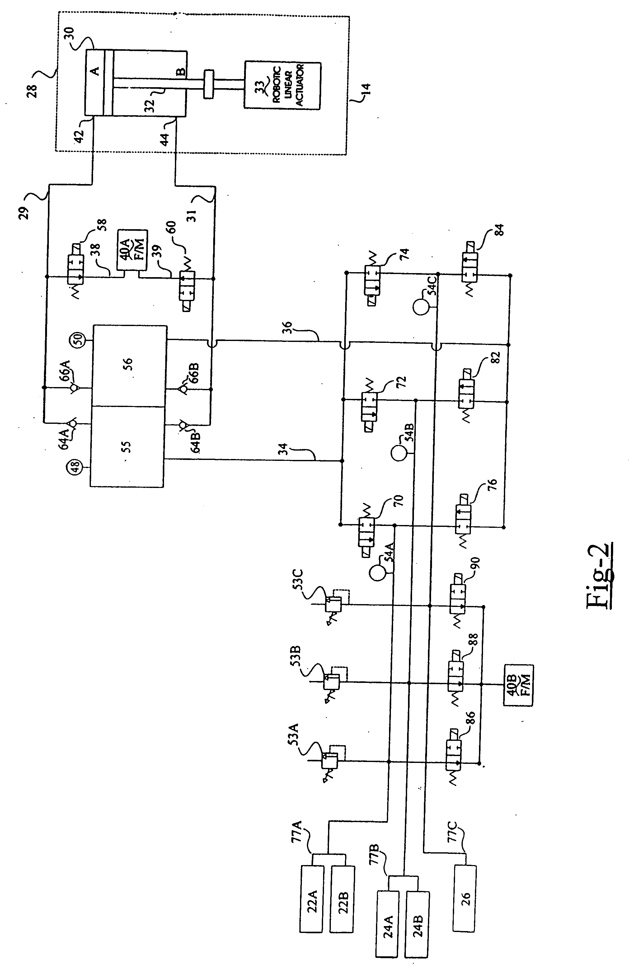
[0024]FIG. 2 schematically illustrates, in greater detail, selected portions of the counterpulsation system. The plurality of inflatable cuffs 22, 24 and 26-are adapted to be placed about the calves, thighs and buttocks of a patient, respectively. The inflatable cuffs are inflated in


PUM


Abstract

A counterpulsation device that operates without the use of compressed air or pressurized gas includes at least one inflatable cuff that is adapted to be placed about a selected portion of the patient's body. A conduit connects the inflatable cuff to an air transfer device so that noncompressed air can be transferred from the air transfer device to the cuff through the conduit to inflate the cuff. The conduit also connects the cuff to the air transfer device so that air can flow through the conduit to deflate the cuff. Another conduit is coupled to the first so that the air in the system can be selectively vented into the atmosphere.. A series of valves are placed on the conduit to selectively control whether air is supplied to or withdrawn from the inflatable cuff. The air moving device preferably is a cylinder having a piston that moves through the cylinder to move the air from within the cylinder through the conduit and into or out of the cuff as desired. The piston moves through the cylinder through the use of a linear servo actuator that is controlled by an appropriately programmed electronic controller so that the inflation of the cuff is timed with portions of the patient's EKG signal and peripheral plethysmographic wave.

Description


Claims


Application Information

Patent Timeline
Owner CPCA2000
Why Eureka
Try Eureka