Lumbar pillow

a pillow and lumbar technology, applied in the field of pillows, can solve the problems of extending the time for recovery of soft tissue injury, back pain is a common problem experienced by many people, etc., and achieve the effect of achieving the curvature of the spin

Inactive Publication Date: 2006-04-13
DUPONT ISABELLE
View PDF14 Cites 4 Cited by
  • Summary
  • Abstract
  • Description
  • Claims
  • Application Information

AI Technical Summary

Benefits of technology

This patent describes a device called Lumbar Pillows that helps support the lower part of your body during rehabilitation after injury or surgery. It consists of a unitary frame made up of two wings joined by an arc on one side. These wings have a curved shape that fits around the person's waist. They also fill certain parts of their back like bone structures. When they are put down, these devices help them get out of bed comfortably.

Problems solved by technology

The technical problem addressed in this patent is how to prevent back pain caused by poor postures due to weakened muscles around the lower part of the body's neck called the lumber region (the portion where the spinal cord connects between two parts). Existing methods like braces are often uncomfortable because they can cause damage to the patient's own skin. There is also a risk of causing complications during treatment procedures. Therefore there is a need for a solution that allows for more comfortable and effective ways to compress the shoulder area while applying pressure to treat back pain.

Method used


Image

  • Lumbar pillow
  • Lumbar pillow
  • Lumbar pillow

Examples


Embodiment Construction

[0012] In this specification a same feature or component may be identified by a same number and / or the number plus.

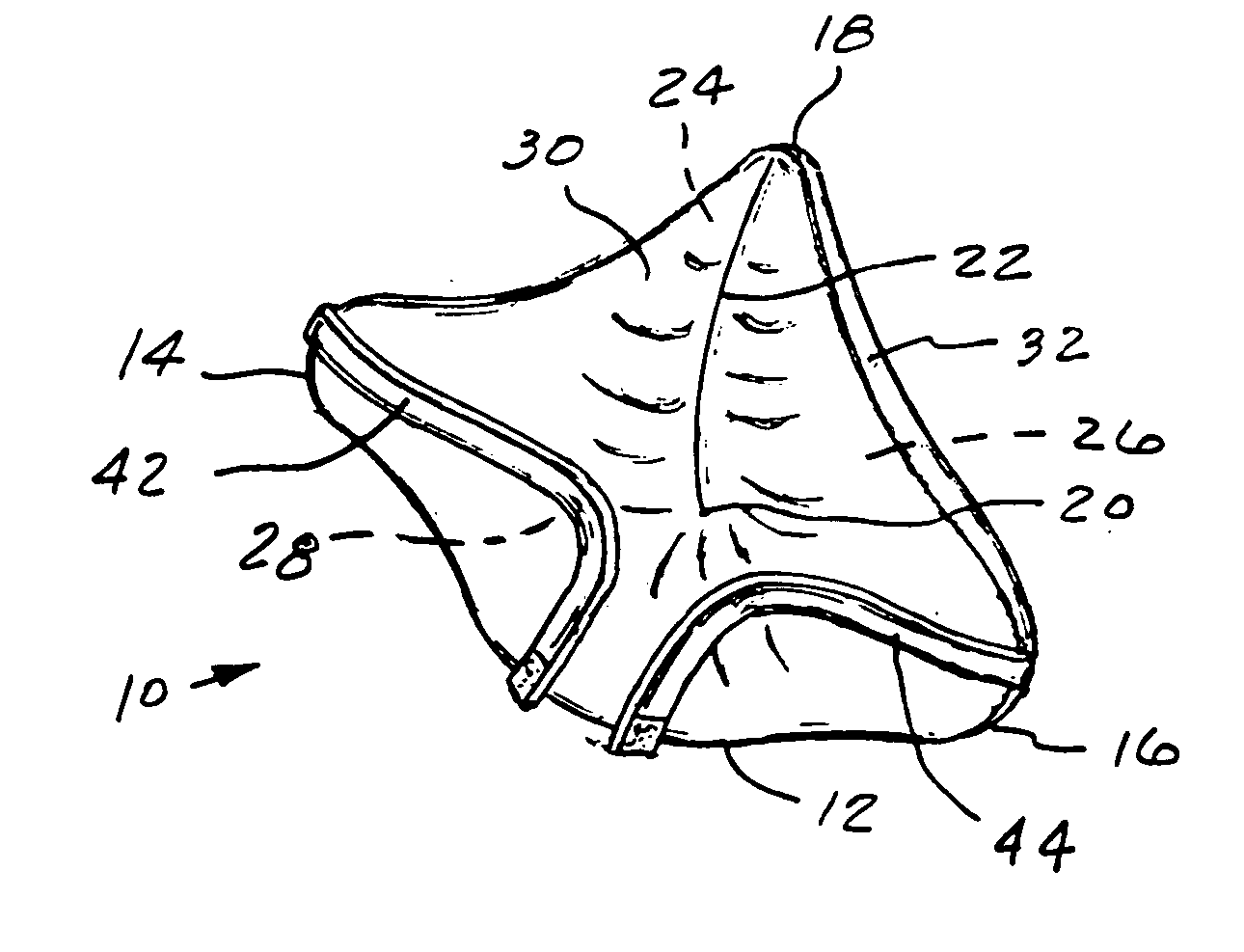
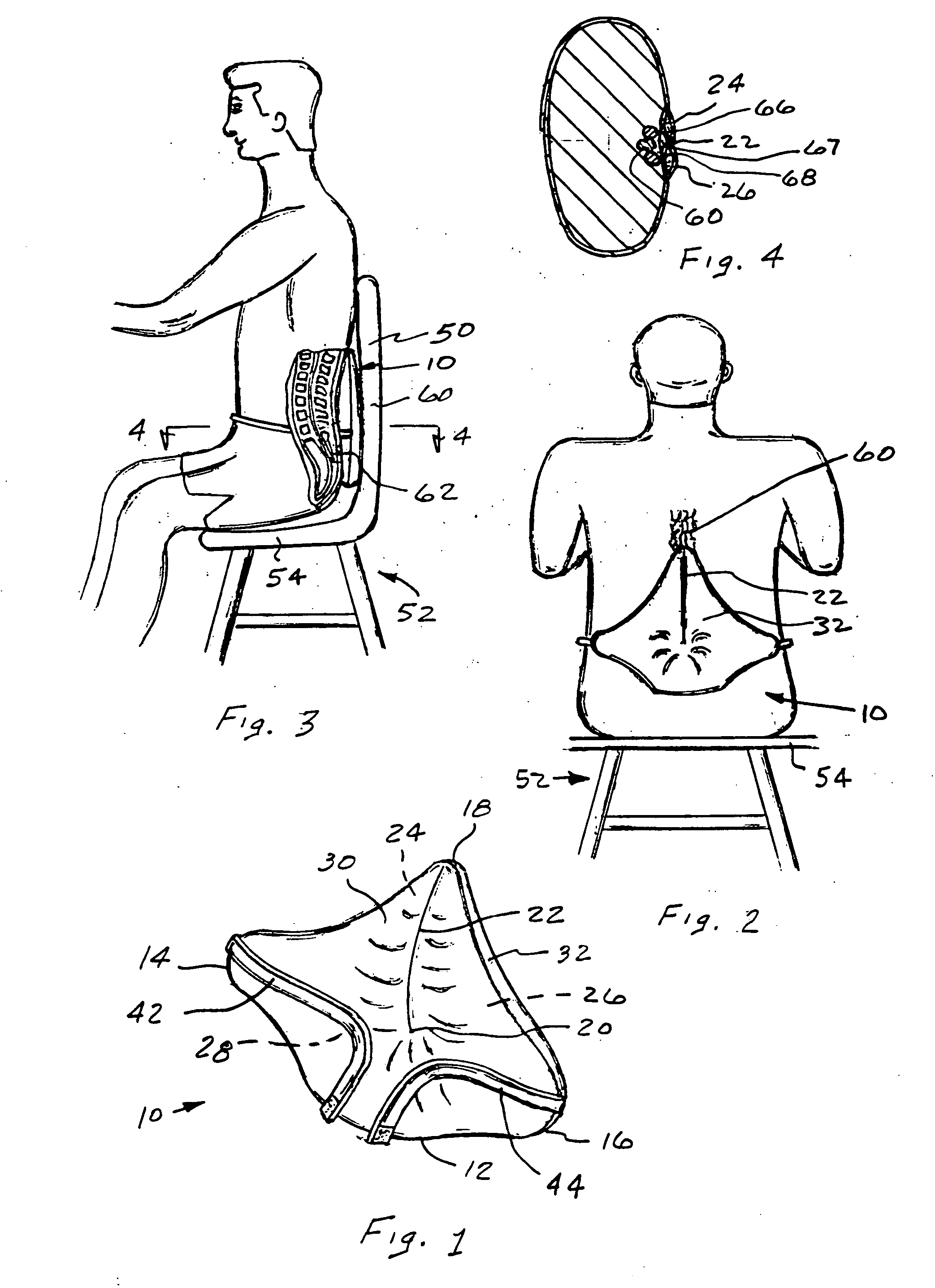
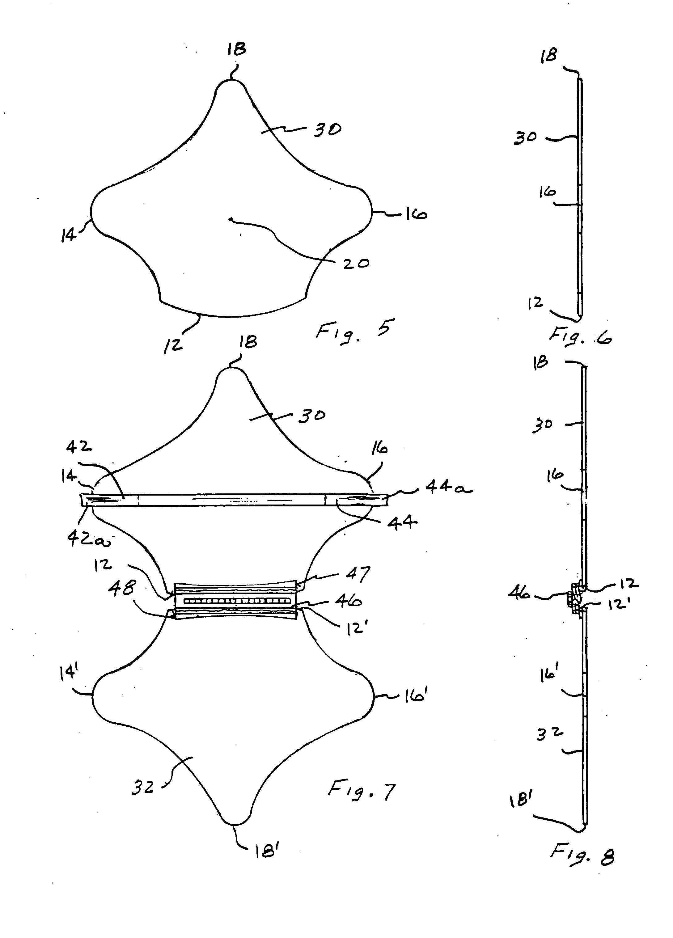
[0013] The lumbar pillow 10 of the present invention shown in FIG. 1 is designed to provide an individual with a means to selective apply pressure the soft tissue that surrounds the lumbo vertebrae 60 of the spine. The pillow 10 is reversible and distinguished by a unitary structure having a peripheral shape defined by an arcuate base 12 that transition into identical first 14 and second 16 wings that are connected to an apex 18 that is located along a radial plane that extends from the center 20 of the radius for the arcuate base 12. The apex 18 is in perpendicular alignment with a horizontal plane that extends through the first 14 and second 16 wings and has a seam 22 that extends from the apex 18 to the center 20 of the radius to define between a first member 30 and a second member 32, first 24 and second 26 spaces or areas that are connected together by an arcuate s


PUM


Abstract

A lumbar pillow through which a force is transmitted into a lumbar area of the spine of an individual. The lumbar pillow has a housing with an interior divided by a seam extends from an apex to a center of a radius for an arcuate base and filled with a resilient material. The lumbar pillow is aligned on an individual with the seam is positioned over the second and third lumbo vertebrae and the arcuate base covering the lumbo-sacral junction of the spine. Thereafter, when the resilient material is compressed a force is primarily directed into soft tissue areas adjacent the lumbo vertebrae to assist in obtaining a desired curvature for the spine.

Description


Claims


Application Information

Patent Timeline
Owner DUPONT ISABELLE
Why Eureka
Try Eureka