Method for Enhancing Ground-Based Detection of a Moving Object

a technology for moving objects and ground detection, applied in image enhancement, television systems, instruments, etc., can solve problems such as degraded noise rejection capabilities, and achieve the effect of reasonable processing load and maximized detection probability for the system

Inactive Publication Date: 2009-06-25
THE UNITED STATES OF AMERICA AS REPRESENTED BY THE SECRETARY OF THE NAVY
View PDF6 Cites 16 Cited by
  • Summary
  • Abstract
  • Description
  • Claims
  • Application Information

AI Technical Summary

Benefits of technology

The technical effect of this patented technology allows us to determine how many times an object has been detected within images without exceeding its maximum detectable range or reducing sensitivity at certain points during the analysis time. By adjustting these thresholds based on factors like resolution, type of sensor used, etc., we can improve accuracy even when analyzing longer periods of data.

Problems solved by technology

The technical problem addressed by this patented technology relates to improving motion detection accuracy while reducing interference between strong signals like sunlight and other sources such as street lights caused by glare on images captured through cameras used during daytime activities.

Method used


Image

  • Method for Enhancing Ground-Based Detection of a Moving Object
  • Method for Enhancing Ground-Based Detection of a Moving Object
  • Method for Enhancing Ground-Based Detection of a Moving Object

Examples


Embodiment Construction

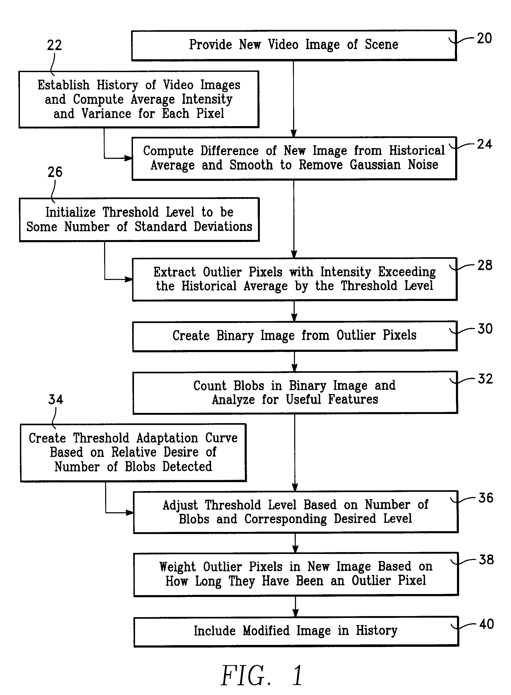
[0020]Referring first to FIG. 1, there is shown a flow chart which depicts a method for enhancing ground-based detection of a moving object comprising the present invention. The method illustrated by the flow chart of FIG. 1 is designed to accurately and consistently locate bright, moving objects within the FOV (field of view) by analyzing a sequence of digital images captured by a sensor, while minimizing the effects of undesired background clutter. For the method illustrated in FIG. 1, the image characteristics of importance are (1) the level of contrast between the objects of interest and the background, and (2) the motion of the objects of interest apparent to the sensor observing movement by the objects of interest. To exploit these characteristics, the method of FIG. 1 is designed to extract those objects from a scene that are bright and exhibiting adequate motion to detect movement. However, parameters can be changed that would allow extraction of dark objects, or objects exhibi


PUM


Abstract

A method for enhancing detection of a moving object. The method includes comparing a video image to a historical sequence of images obtained from the same scene or stationary source. The method uses statistical sampling to implement change detection and thresholding operations which extract moving objects from the scene. The method provides for a high degree of sensitivity and noise rejection to motion detection, and is self-adapting to variations in sensor characteristics and operating environments.

Description


Claims


Application Information

Patent Timeline
Owner THE UNITED STATES OF AMERICA AS REPRESENTED BY THE SECRETARY OF THE NAVY
Why Eureka
Try Eureka