Method and system for non-contact powder image development

a non-contact powder and image technology, applied in the field of non-contact powder image development, can solve the problems of uncontrollable charge, undeveloped image, undeveloped image, etc., and achieve the effect of minimizing the impact of undeveloped particles

Active Publication Date: 2009-09-17
XEROX CORP
View PDF11 Cites 2 Cited by
  • Summary
  • Abstract
  • Description
  • Claims
  • Application Information

AI Technical Summary

Benefits of technology

The present invention provides an improved method for reducing particle impacts during the manufacturing process by optimizing the speed at which the particles hit the surface being treated.

Problems solved by technology

The technical problem addressed in this patent is how to efficiently fluidize toners without causing any unwanted artifacts during the process. Current solutions involve replacing the wires with other materials like metal foils, but there may be issues with current methods due to the accumulation of deposits on the wires themselves.

Method used


Image

  • Method and system for non-contact powder image development
  • Method and system for non-contact powder image development
  • Method and system for non-contact powder image development

Examples


Embodiment Construction

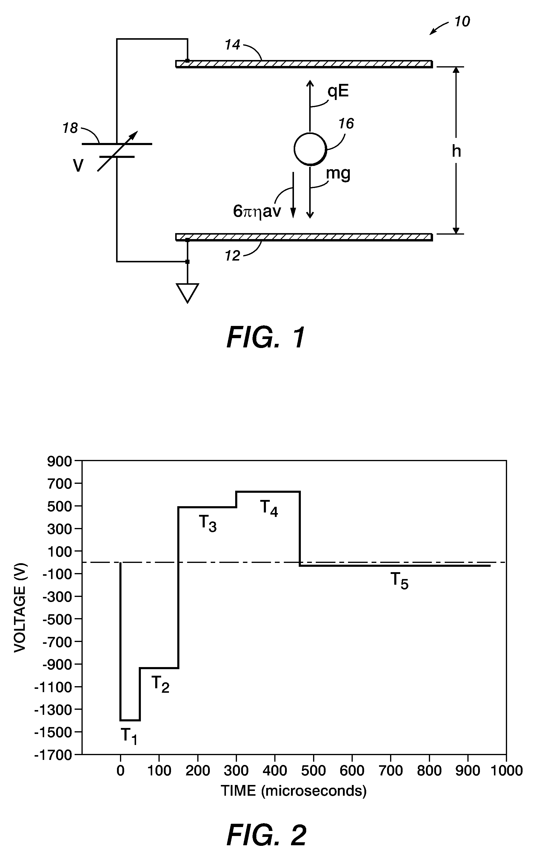
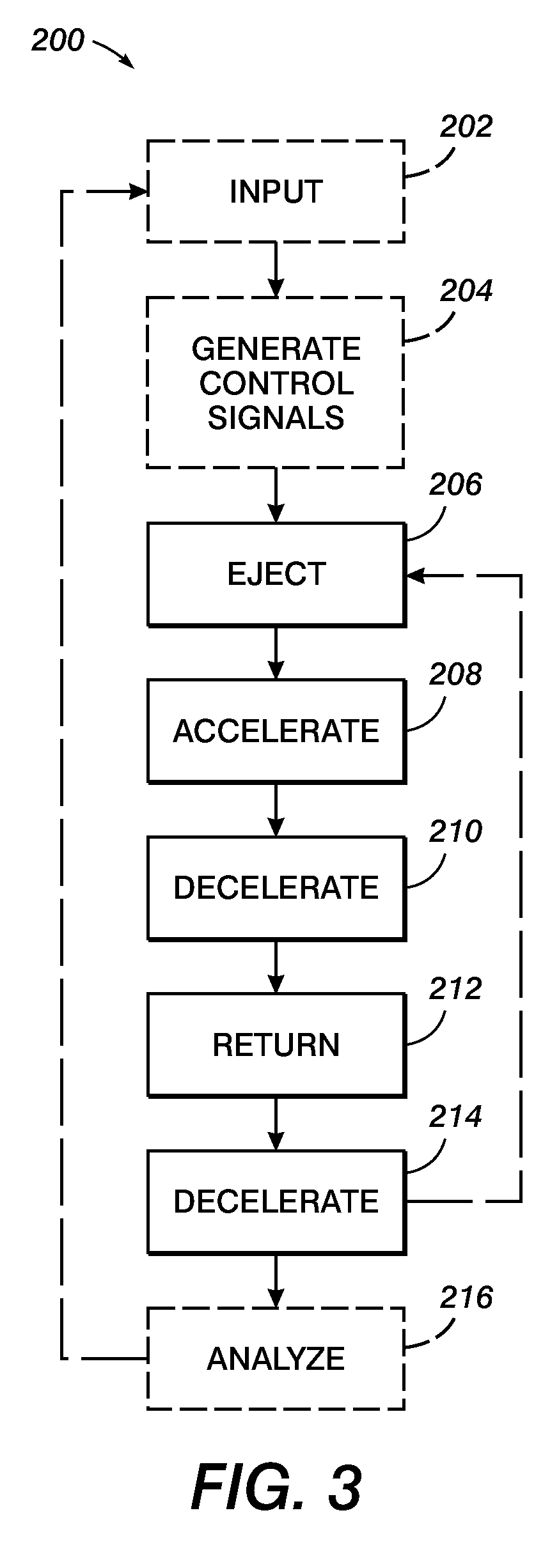
[0030]The presently described embodiments improve upon the prior noted wireless method(s) in at least the following respects: (1) a 5-stage jumping development cycle is implemented where the initial stage is a momentary over-voltage condition to release the majority of the toner on a donor substrate and the final stage includes the implementation of a decelerating potential to minimize the return impact on the donor and, therefore, toner abuse; and (2) a routine is used to directly determine improved (e.g. up to optimal) waveform amplitudes and pulse widths based on toner size and q / m, guided by physical insight. In at least one form, the routine allows for an automation of the process.

[0031]In this regard, given a distribution of particle size and charge, detachment forces have to act over a wide range to overcome the nonlinear adhesion forces of the donor surface to fluidize particles. The contemplated momentary overvoltage serves to so detach the majority of particles with a high


PUM


Abstract

An improved method and system for non-contact powder image development are provided. The present technique implements a 5-stage jumping development cycle where the initial stage is a momentary over-voltage condition to release the majority of the toner on a donor substrate and the final stage includes the implementation of a decelerating potential to minimize return impact on the donor and therefore toner abuse. It also uses a routine to directly determine improved (e.g. up to optimal) waveform amplitudes and pulse widths based on toner size and q/m, guided by physical insight.

Description


Claims


Application Information

Patent Timeline
Owner XEROX CORP
Why Eureka
Try Eureka