Outer mirror
- Summary
- Abstract
- Description
- Claims
- Application Information
AI Technical Summary
Benefits of technology
Problems solved by technology
Method used
Image

Examples
first embodiment
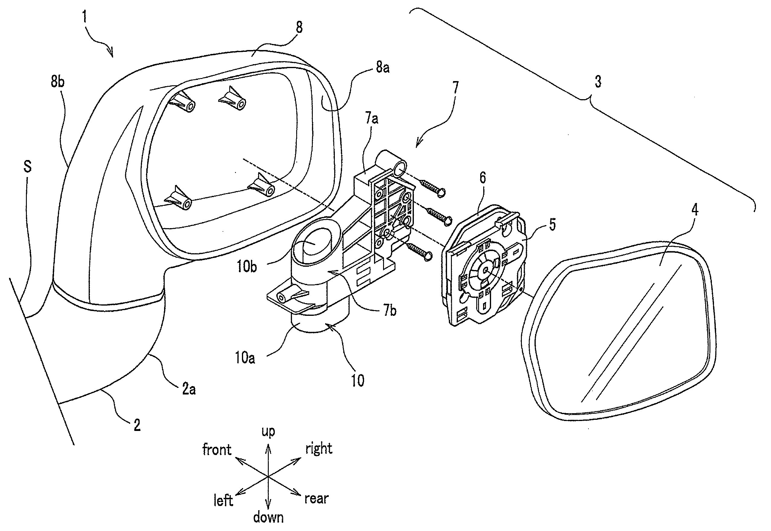
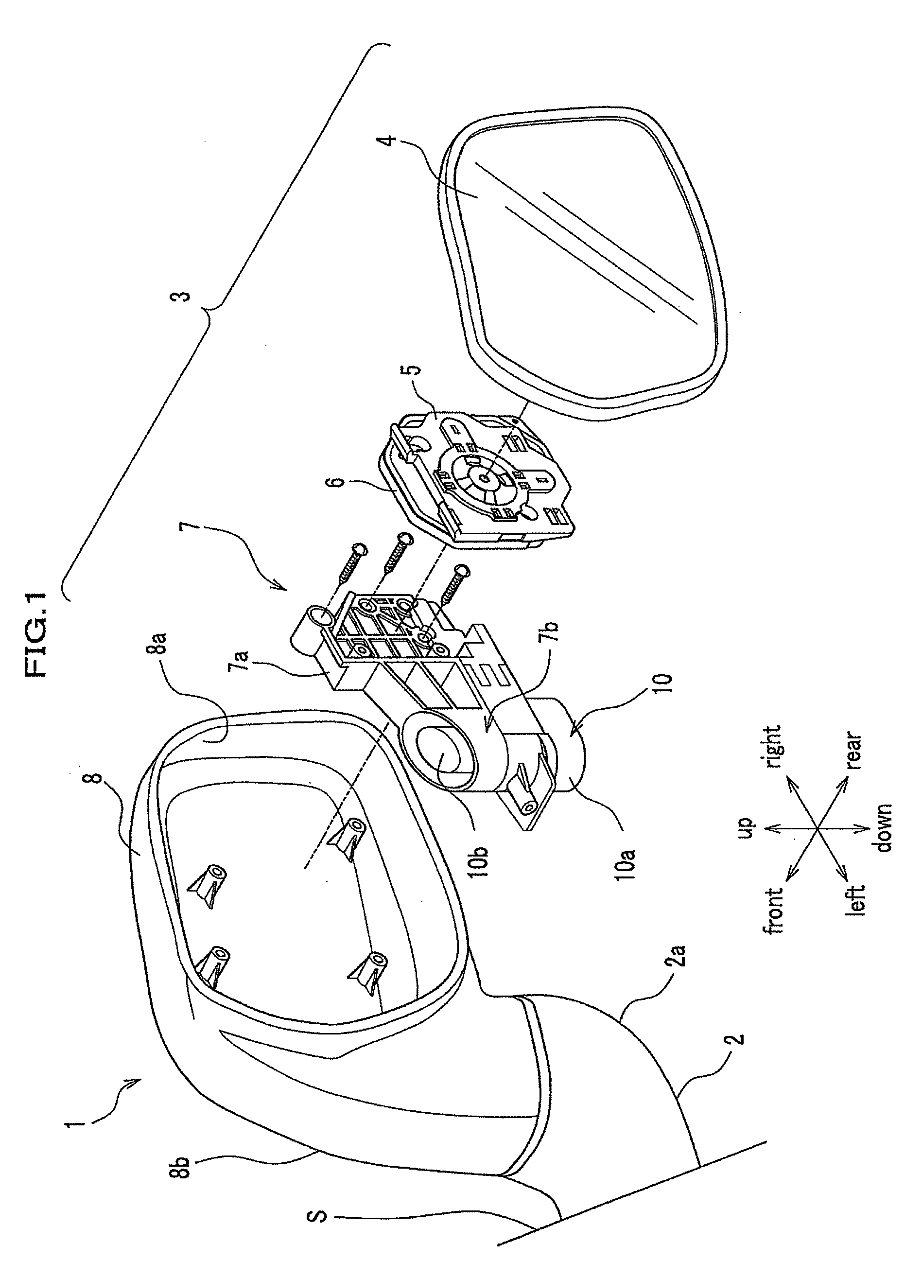
[0035]As shown in FIG. 1, the outer mirror 1 according to the first embodiment is a so-called door mirror attached to a surrounding area on a side door of a vehicle body S, and includes a mirror base 2 extending laterally from a side face of the vehicle body S, a shaft body 10 fixed to the mirror base 2, and a mirror assembly 3 horizontal-rotatably mounted on the mirror base 2 around the shaft body 10 used as a rotational axis. As shown in FIG. 3, in the outer mirror 1, a windshield member 20 is provided at a gap K between the mirror base 2 and the mirror assembly 3.
[0036]The mirror base 2 supports the mirror assembly 3. As shown in FIGS. 1 and 3, the mirror base 2 is formed to project in the upward oblique direction from the side face of the vehicle body S. In this embodiment, the mirror base 2 includes a tube portion 2a projecting from the vehicle body S in the upward oblique direction like an arc, and an upper plate portion 2b to occlude a front edge of the tube portion 2a. An elect
second embodiment
[0055]FIG. 4A is an enlarged sectional view of a windshield member according to the second embodiment. FIG. 4B is a perspective view of the windshield member according to the second embodiment.
[0056]As shown in FIG. 4, an outer mirror 1′ according to the second embodiment differs from the outer mirror 1 according to the first embodiment in that a mirror base 30 is provided with a cover 40, and that a windshield member 20′ is provided.
[0057]The mirror base 30 is formed to extend laterally from a side face of a vehicle body S, and supports the mirror assembly 3 from below. The mirror base 30 shows a tabular appearance, and includes a lower plate portion 30a extending from the vehicle body S, an upper plate portion 30b likewise extending from the vehicle body S, and a side plate portion 30c to connect the lower plate portion 30a and the upper plate portion 30b.
[0058]The inside of the mirror base 30 is formed to be hollow, and the electric cord C is provided through an insertion hole 30d
third embodiment
[0065]FIG. 5A is an exploded perspective view of an outer mirror according to the third embodiment. FIG. 5B is an enlarged sectional view of a windshield member according to the third embodiment.
[0066]As shown in FIG. 5, an outer mirror 200 according to the third embodiment differs from the outer mirror 1 according to the first embodiment in that a mirror base 202 is provided with a base plate 202b.
[0067]The outer mirror 200 according to the third embodiment includes a mirror base 202 having a base plate 202b, a shaft body 210 fixed to a mirror base 202, and a mirror assembly 203 which rotates around the shaft body 210 used as a rotational axis and which has a housing 208. In the housing 208, an opening 208c toward the mirror base 202 is formed.
[0068]The mirror base 202 is provided with a supporting portion 202e extending laterally from a mounting portion 202d attached to a vehicle body (not shown). The supporting portion 202e is provided with a concave portion 202a, the configuration
PUM
 Abstract
Description
Claims
Application Information
 - R&D Engineer
- R&D Manager
- IP Professional
- Industry Leading Data Capabilities
- Powerful AI technology
- Patent DNA Extraction
Browse by: Latest US Patents, China's latest patents, Technical Efficacy Thesaurus, Application Domain, Technology Topic.
© 2024 PatSnap. All rights reserved.Legal|Privacy policy|Modern Slavery Act Transparency Statement|Sitemap