Abs hydraulic unit

Inactive Publication Date: 2015-08-27
ROBERT BOSCH GMBH
View PDF5 Cites 1 Cited by
  • Summary
  • Abstract
  • Description
  • Claims
  • Application Information

AI Technical Summary

Benefits of technology

[0007]According to the invention, it is possible to realize an ABS hydraulic unit which can reduce a use amount of a b

Problems solved by technology

Further, the block becomes large and hence, the ABS hydraulic unit becomes large and heavy.
Further, in manufacturing steps of such an ABS hydraulic unit, it is necessa

Method used


Image

  • Abs hydraulic unit
  • Abs hydraulic unit
  • Abs hydraulic unit

Examples


Embodiment Construction

[0017]Hereinafter, one preferred embodiment of the invention is explained with reference to drawings.

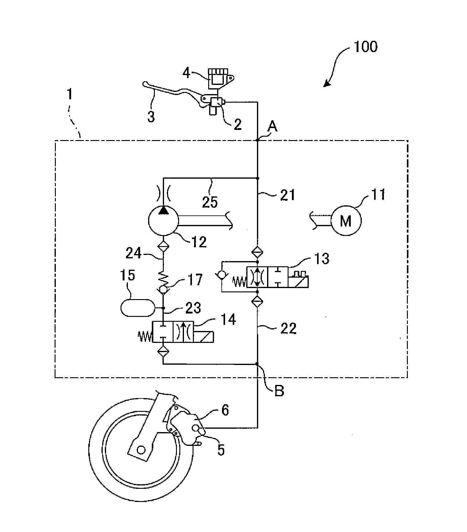
[0018]FIG. 1 is a circuit diagram showing a hydraulic circuit of an ABS hydraulic unit according to this embodiment. In a motorcycle according to this embodiment, an ABS (anti-lock braking system) is mounted only on a front wheel so that the ABS hydraulic unit 100 can perform an antilock brake control only with respect to the front wheel. Hereinafter, a hydraulic circuit 1 for the front wheel is explained.

[0019]The hydraulic circuit 1 is filled with a brake fluid, and is connected to a master cylinder 2 at a first connection end A thereof. A brake lever 3 is mounted on the master cylinder 2, and the master cylinder 2 is connected to a reservoir 4. Due to such a constitution, when a rider manipulates the brake lever 3 so as to apply braking to the front wheel, the master cylinder 2 discharges a brake fluid accumulated in the reservoir 4 into the hydraulic circuit 1.

[0020]On the other han


PUM


Abstract

An ABS hydraulic unit (100) where a hydraulic circuit (1) is connected to a master cylinder for discharging a brake fluid at a first connection end (A) thereof and is connected to a hydraulic brake at a second connection end (B) thereof, and makes the hydraulic brake perform braking, a pump (12) operated by a motor, a closing valve (13), a release valve (14) and an accumulator (15) are provided in the hydraulic circuit (1), and an antilock brake control of the hydraulic brake is performed by controlling the pump (12), the closing valve (13) and the release valve (14), wherein the ABS hydraulic unit (100) has a circuit part (50a) in which the hydraulic circuit (1) is disposed, the circuit part (50a) includes: a discharge side passage where the pump (12) is disposed at one end of the discharge side passage in a longitudinal direction and the first connection end (A) is formed on the other end of the discharge side passage in the longitudinal direction, and connects a discharge side of the pump (12) and the first connection end (A) to each other; and a suction side passage which extends along the discharge side passage and connects a suction side of the pump (12) and the closing valve (13) to each other, and the accumulator (15), the release valve (14), the second connection end (B) and the closing valve (13) are arranged in the suction side passage in order from one end to the other end.

Description


Claims


Application Information

Patent Timeline
Owner ROBERT BOSCH GMBH
Why Eureka
Try Eureka