Electrolytic deburring apparatus and method

Inactive Publication Date: 2010-03-25
KENNAMETAL INC
View PDF1 Cites 6 Cited by
  • Summary
  • Abstract
  • Description
  • Claims
  • Application Information

AI Technical Summary

Benefits of technology

[0008]The present invention provides toolless electrolytic deburring methods and associated apparatuses that overcome at least some of the aforementioned drawbacks of the prior art. In particular, the methods and apparatuses of the present invention are particularly well-suited for toolless electrolytic deburring of individual workpieces, especially those which have areas that need more processing than other areas. The present

Problems solved by technology

A significantt amount of electrolyte loss may occur when the workpieces are pulled out of the electrolyte bath.
Another drawback is that fixturing is usually necessary to hold the workpiece in place during the process.
The fixtures gradually electrochemically dissolve away during use and scratches and other surface defects on a fixture can locally accelerated the electrochemical dissolution rate, shortening the fixture's useful lifetime.
Another drawback is that while the conventional toolless electrolytic deburring process is well-suited to the simultaneous processing of multiple workpieces in production quantities,

Method used


Image

  • Electrolytic deburring apparatus and method
  • Electrolytic deburring apparatus and method
  • Electrolytic deburring apparatus and method

Examples


Embodiment Construction

[0017]In this section, some preferred embodiments of the present invention are described in detail sufficient for one skilled in the art to practice the present invention. It is to be understood, however, that the fact that a limited number of preferred embodiments are described herein does not in any way limit the scope of the present invention as set forth in the appended claims.

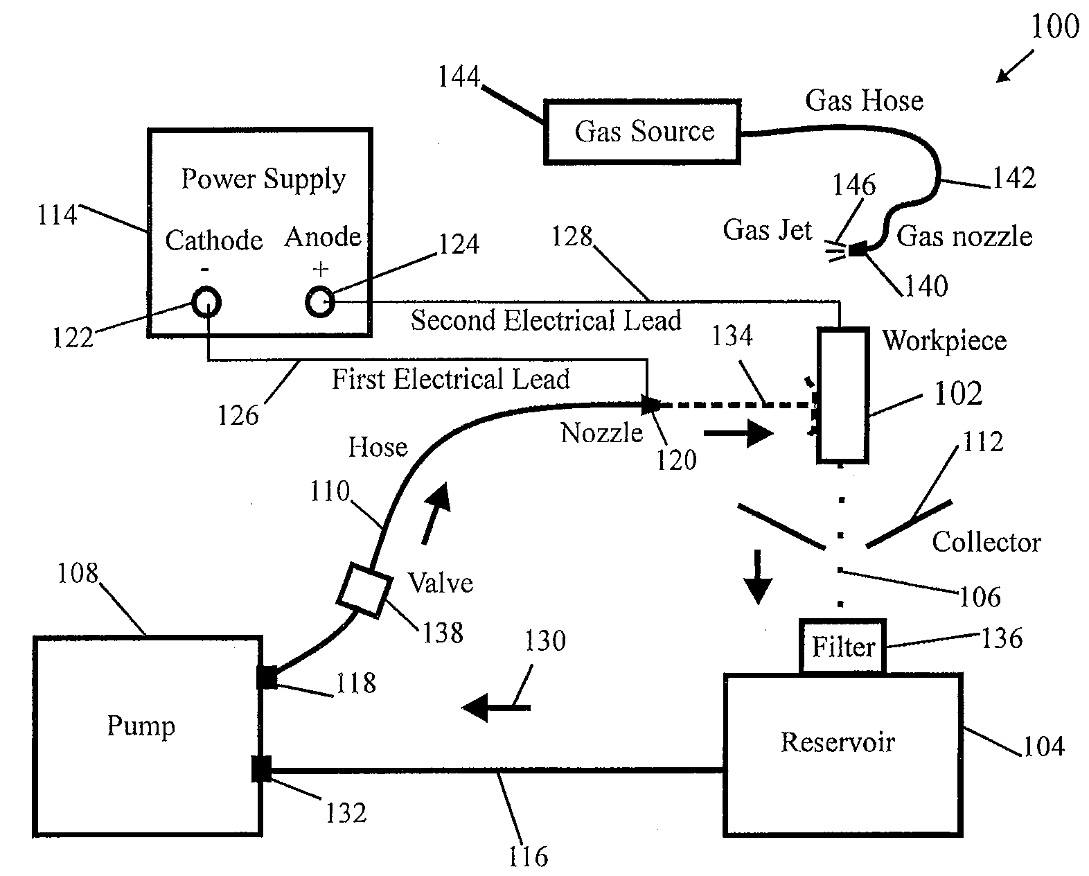
[0018]Referring to FIG. 1, there is shown a schematic representation of an apparatus 100 for toolless electrolytic deburring of a metal workpiece 102 according to an embodiment of the present invention. The apparatus 100 comprises a reservoir 104 containing a quantity of electrolyte 106, a pump 108, a flexible hose 110, a collector 112, and an electrical power supply 114 that is adapted to provide DC current, preferably pulsed DC current. The reservoir 104 is in fluid communication with the pump 108 via a pipe 116. One end of the hose 110 is operably connected to the pump outlet 118 and the other end is attac


PUM

PropertyMeasurementUnit
Poweraaaaaaaaaa
Flow rateaaaaaaaaaa
Currentaaaaaaaaaa

Abstract

Apparatuses and methods for toolless electrolytic deburring are disclosed in which a charged electrolyte stream flows through a hose and nozzle and can be selectively directed at a desired portion of an external or internal surface of a workpiece. The nozzle or the workpiece can be manipulated to vary the electrolytic deburring working gap so as to control the intensity of the electrolytic deburring and the portion of the workpiece that is electrolytically deburred. The electrolytic deburring is preferably performed in an enclosure having a glove which has an electrical contact that can be used to electrically connect the workpiece to the DC power supply anode simply by gripping the workpiece.

Description


Claims


Application Information

Patent Timeline
Owner KENNAMETAL INC
Why Eureka
Try Eureka