Network relay apparatus and inter-network relay method
- Summary
- Abstract
- Description
- Claims
- Application Information
AI Technical Summary
Benefits of technology
Problems solved by technology
Method used
Image

Examples
first embodiment
Configuration of Multicast Network
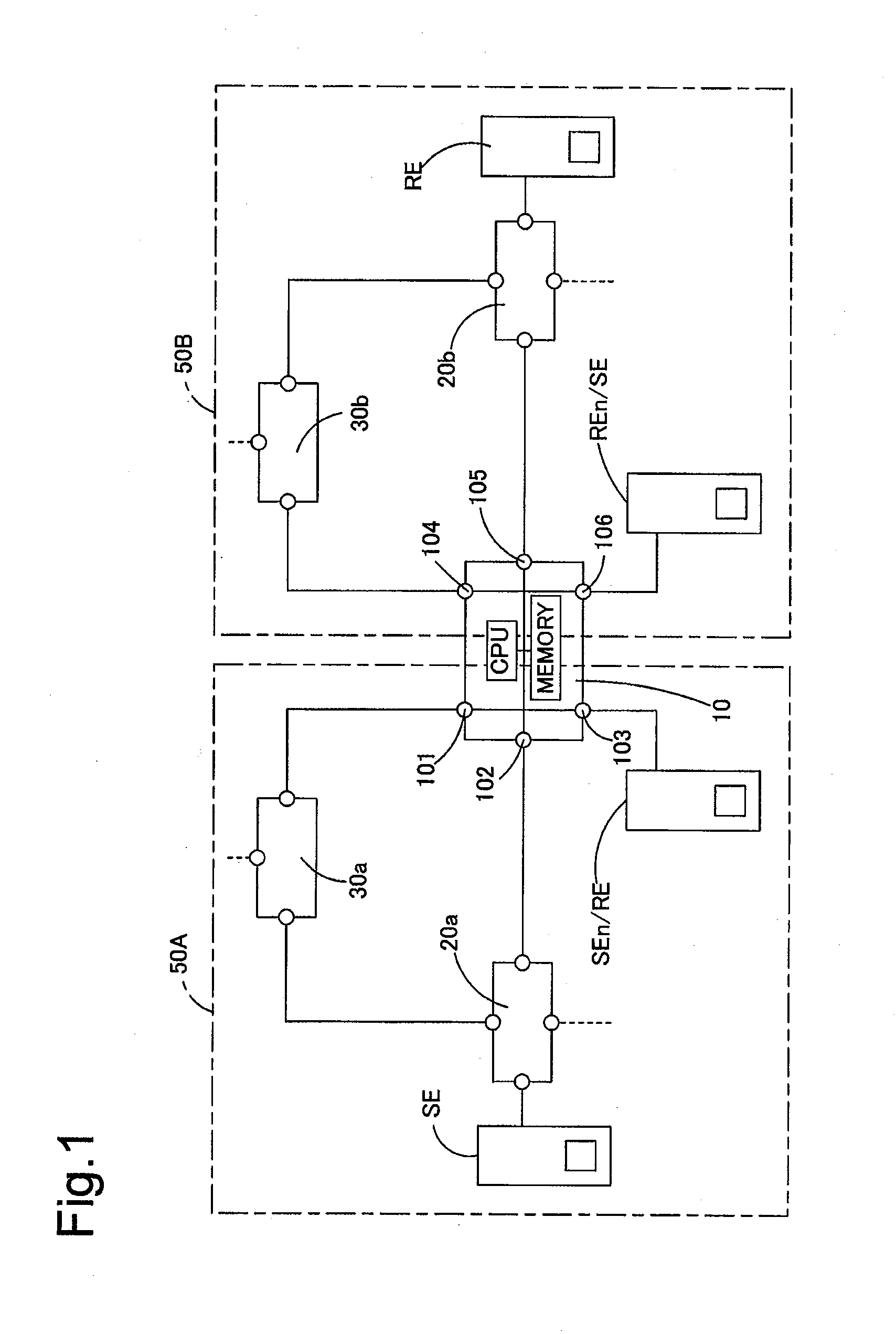
[0054]FIG. 1 is an explanatory diagrammatic representation of a multicast network configuration according to a first embodiment of the invention. A network relay router 10 as one embodiment of the network relay apparatus according to the invention establishes and has a first VPN (virtual private network) 50A and a second VPN 50B. Each of the first and the second VPNs 50A and 50B forms a PIM-SM multicast network. The first VPN 50A is constructed by routers 20a and 30a and the network relay router 10, wherein the router 30a functions as a rendezvous point. The second VPN 50B is constructed by routers 20b and 30b and the network relay router 10, wherein the router 30b functions as a rendezvous point. The first VPN 50A and the second VPN 50B respectively correspond to the first network and the second network in the claims of the invention.
[0055]In the first VPN 50A, the router 30a functioning as the rendezvous point is connected with the router 20a and the
second embodiment
[0108]Inter-VRF multicast relay in a network configuration where a transmission device SE and a receiving device RE of multicast packets are directly connected to a network relay router 10 establishing multiple VPNs is described as a second embodiment according to the invention. The network relay router 10 of the second embodiment has the same internal structure as that of the network relay router 10 of the first embodiment. The like components are expressed by the like numerals and symbols and are not specifically described here.
[0109]FIG. 20 is an explanatory diagrammatic representation of the network configuration where the transmission device SE and the receiving device RE of multicast packets are directly connected to the network relay router 10 establishing the multiple VPNs (virtual private networks). The transmission device SE in a first VPN 50A as a first network and the receiving device RE in a second VPN 50B as a second network are connected respectively to an input / output
third embodiment
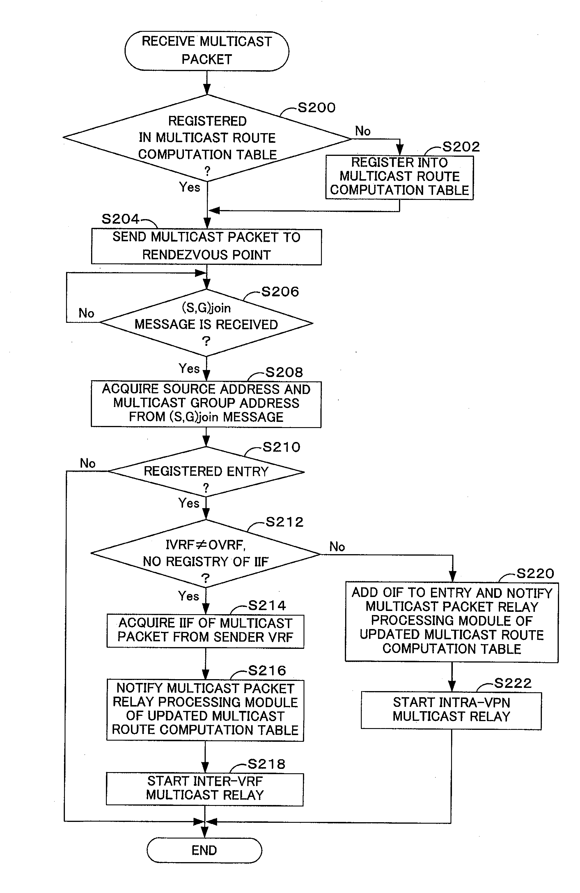
[0120]As in the network configuration of the first embodiment, in a network configuration of a third embodiment according to the invention, a multicast group address as an inter-VRF relay subject, a sender VRF name, and a receiver VRF name are registered in a network relay router 10 establishing or building multiple VPNs. The network relay router 10 of the third embodiment sends a PIM(*,G)join message to a rendezvous point in a sender VPN, in response to reception of a PIM(*,G)join message from a router 20b. Namely the setting of route information in the network relay router 10 alone does not trigger transmission of the PIM(*,G)join message to the rendezvous point in the sender VPN. Namely a multicast packet sent from a transmission device SE is not relayed to the network relay router 10 immediately after completion of the setting. Inter-VRF multicast relay starts after reception of a join request message from a receiving device RE. This arrangement desirably restricts or prevents unne
PUM
 Abstract
Description
Claims
Application Information
 - R&D Engineer
- R&D Manager
- IP Professional
- Industry Leading Data Capabilities
- Powerful AI technology
- Patent DNA Extraction
Browse by: Latest US Patents, China's latest patents, Technical Efficacy Thesaurus, Application Domain, Technology Topic.
© 2024 PatSnap. All rights reserved.Legal|Privacy policy|Modern Slavery Act Transparency Statement|Sitemap