Methods and apparatus for delivering staples to a target tissue

a technology of target tissue and staples, which is applied in the field of orthopedic medicine and surgery, can solve the problems of detachment of the tendon from the bone, damage to the rotator cuff or the rotator cuff tendons, and the damage to the rotator cuff is a potentially serious medical condition, so as to facilitate the bending of each stak

Active Publication Date: 2010-12-09
ROTATION MEDICAL
View PDF103 Cites 79 Cited by
  • Summary
  • Abstract
  • Description
  • Claims
  • Application Information

AI Technical Summary

Benefits of technology

By designing the distance from one part (the top) of two parts - called an anchor or scaffold – towards another part on either side it makes sure they are bent correctly during assembly. However, this created space where no matter how thinly these anchors were made, allowing for flexibility in placement of the legs within them.

Problems solved by technology

The technical problem addressed in this patents is finding ways to improve the stability and effectiveness of prosthetic devices used for shoulder movements while reducing their risk of being worn down due to excessive stress caused by activities like lifter exercise.

Method used


Image

  • Methods and apparatus for delivering staples to a target tissue
  • Methods and apparatus for delivering staples to a target tissue
  • Methods and apparatus for delivering staples to a target tissue

Examples


Embodiment Construction

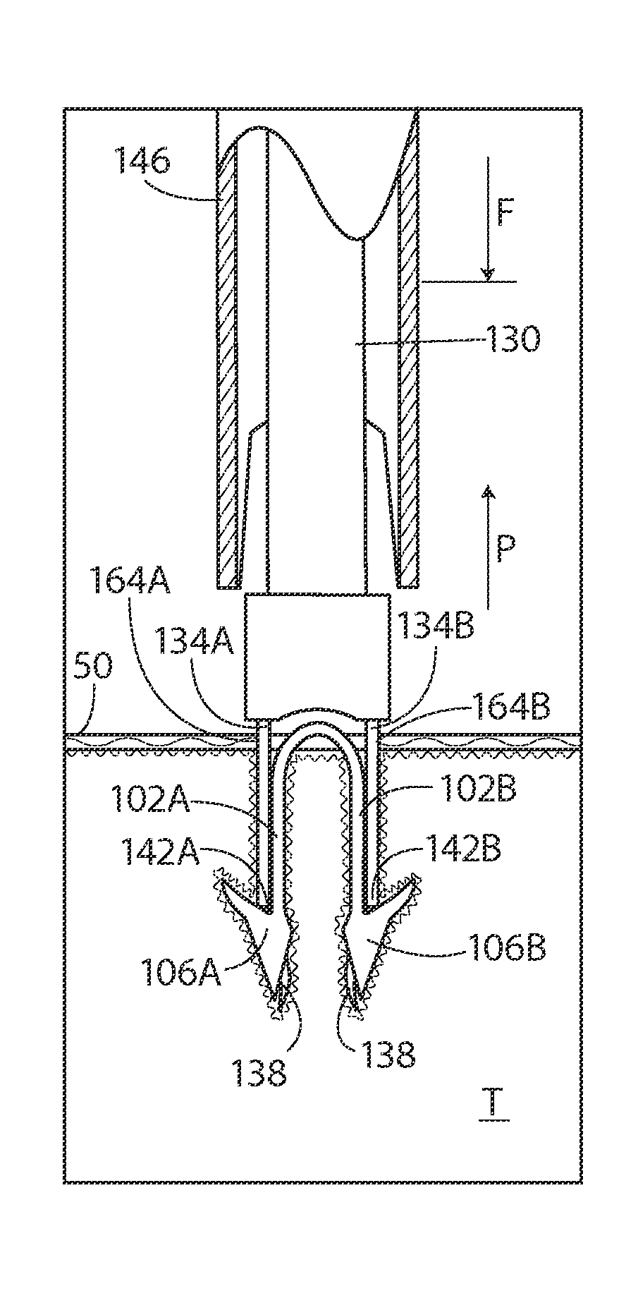
[0042]The following detailed description should be read with reference to the drawings in which similar elements in different drawings are numbered the same. The drawings, which are not necessarily to scale, depict illustrative embodiments and are not intended to limit the scope of the invention.

[0043]As used herein, the term “tissue” refers to soft tissue, such as a tendon, and / or bone tissue, depending on the context in which it is used.

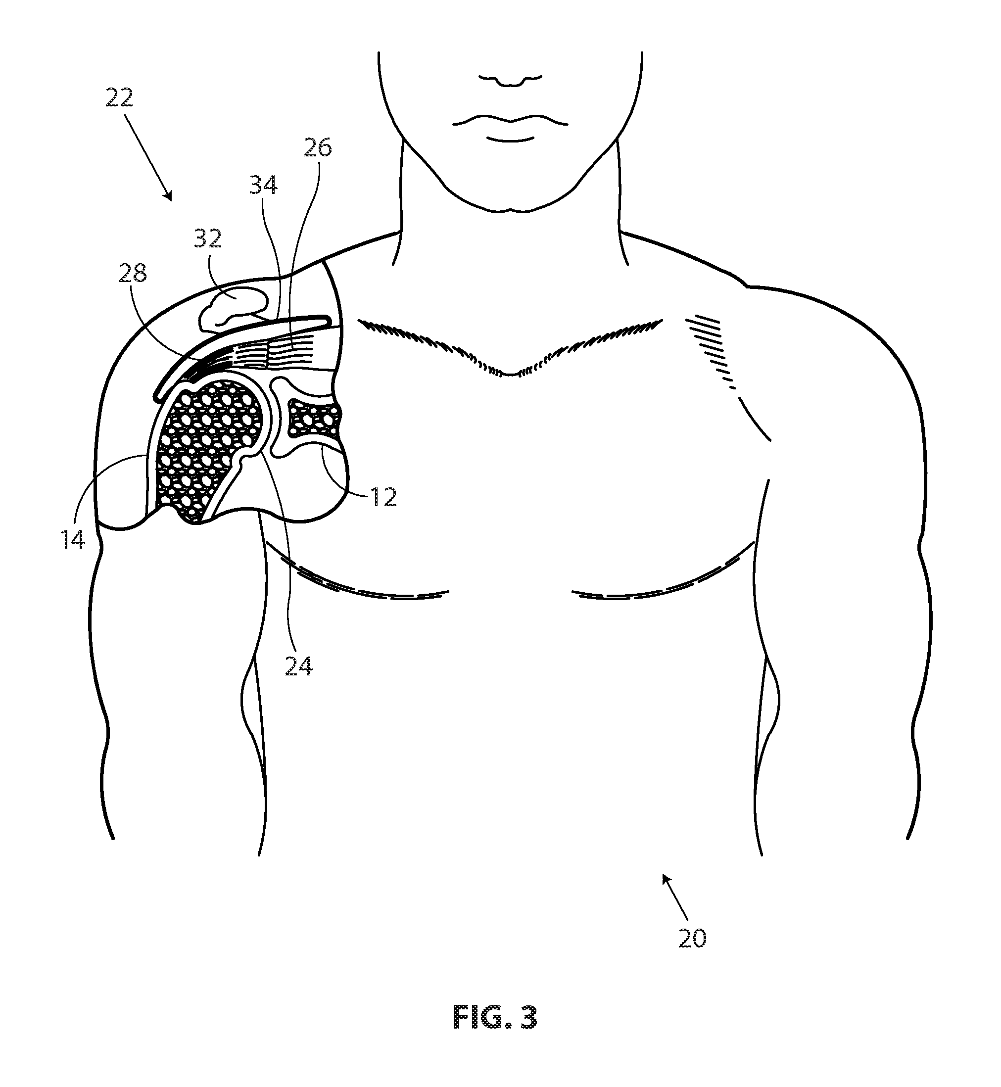
[0044]FIG. 3 is a stylized anterior view of a patient 20. For purposes of illustration, a shoulder 22 of patient 20 is shown in cross-section in FIG. 3. Shoulder 22 includes a humerus 14 and a scapula 12. In FIG. 3, a head 24 of humerus 14 can be seen mating with a glenoid fossa of scapula 12 at a glenohumeral joint. With reference to FIG. 3, it will be appreciated that the glenoid fossa comprises a shallow depression in scapula 12. The movement of humerus 14 relative to scapula 12 is controlled by a number of muscles including: the deltoid, the sup


PUM


Abstract

A device for attaching a sheet-like implant to a target tissue includes a pilot member and a staple push rod. In some embodiments, the pilot member has a distal end and at least a pair of prongs extending from the distal end. The prongs are configured to form pilot holes when the distal end of the pilot member is pressed against the target tissue. The staple push rod is disposed within at least a portion of the pilot member and slidable relative thereto. The staple push rod includes at least a pair of stakes. Each stake is dimensioned to engage a surface of a staple to apply pushing forces thereto. Each stake is positioned relative to a prong along an inner surface of the pilot member so that the stakes advance into the pilot holes when the stakes are moved in a distal direction. Methods for attaching a sheet-like implant to a target tissue are also disclosed

Description


Claims


Application Information

Patent Timeline
Owner ROTATION MEDICAL
Why Eureka
Try Eureka