Light Emitting Diode Selection Circuit
- Summary
- Abstract
- Description
- Claims
- Application Information
AI Technical Summary
Benefits of technology
Problems solved by technology
Method used
Image

Examples
first embodiment
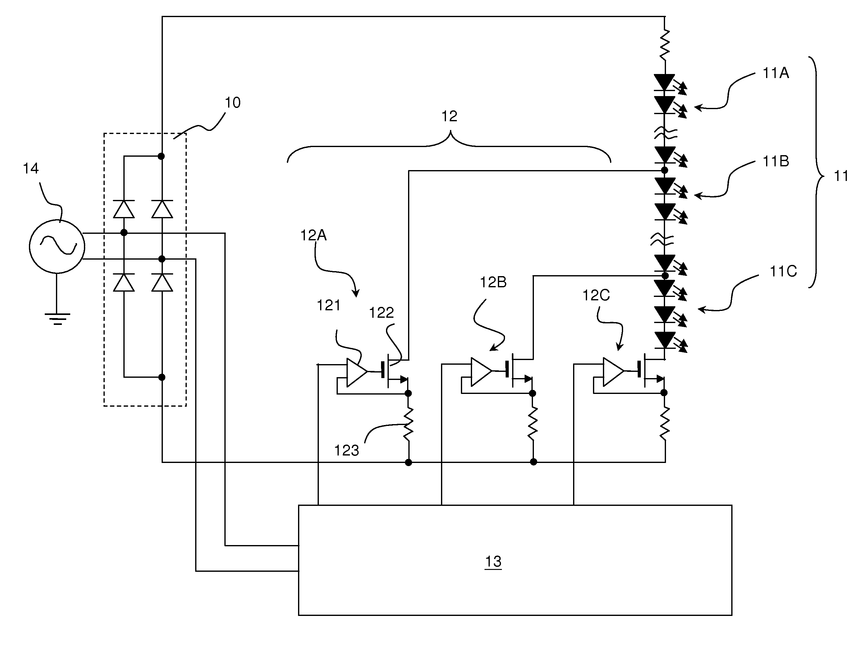
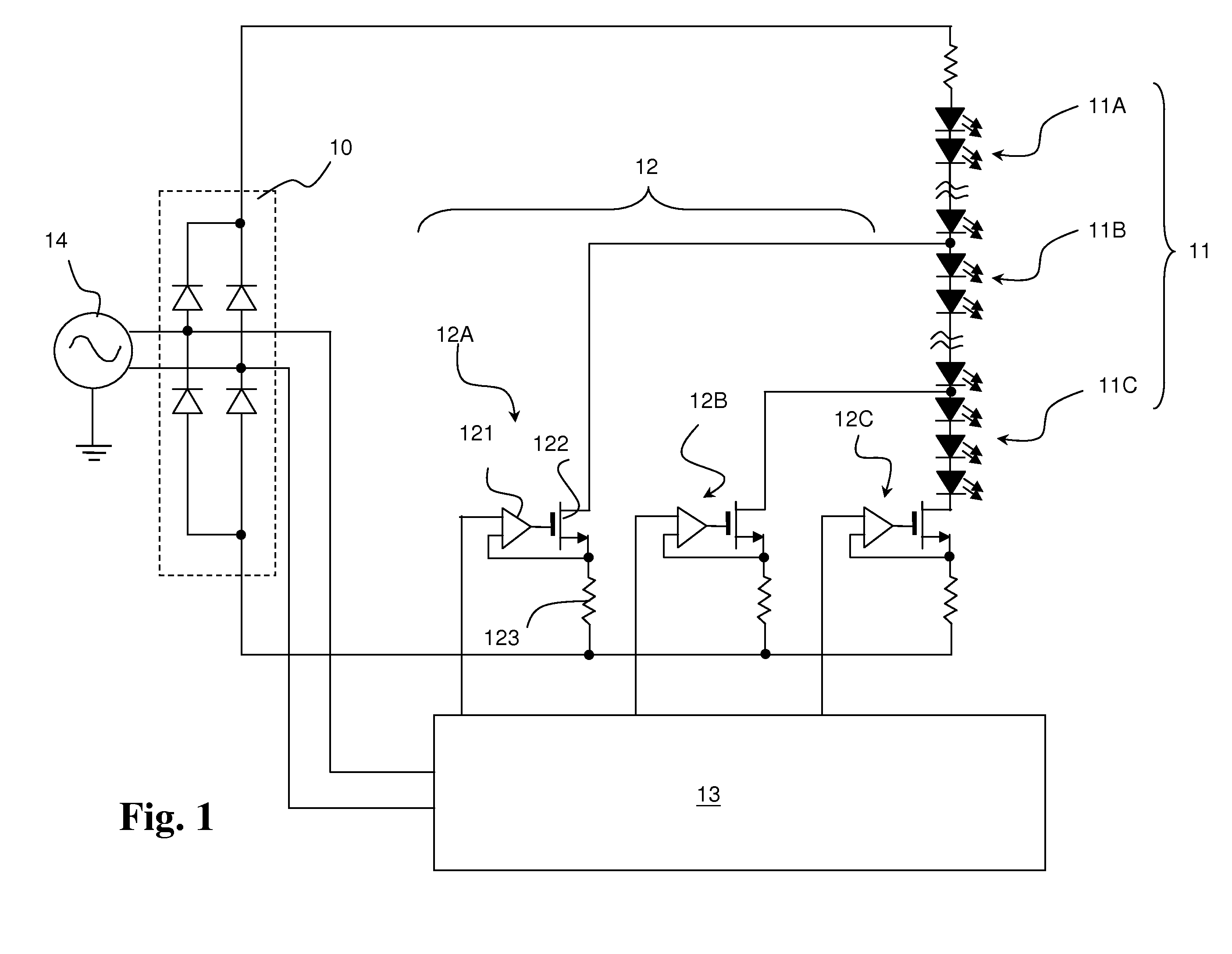
[0018]With reference to FIG. 1, a Light Emitting Diode (LED) selection circuit of an LED driver that drives multiple unequal lengths of LED strings an LED to selectively turn the LED strings ON or OFF corresponding to an input alternating current (AC) line voltage.
[0019]In this embodiment, the LED selection circuit in accordance with the present invention comprises a rectifier (10), multiple LED strings (11), multiple current sources (12) and a controller (13).
[0020]The rectifier (10) is connected to an AC power source (14) and converts an input AC line voltage to a pulsating direct current (DC) voltage.
[0021]The multiple LED strings (11) may comprise a first LED string (11A), a second LED string (11B) and a third LED string (11C). The multiple current sources (12) correspond to the LED strings (11) and may comprise a first current source (12A), a second current source (12B) and a third current source (12C). However, people skilled in art will know the numbers of LED strings (11) and t
second embodiment
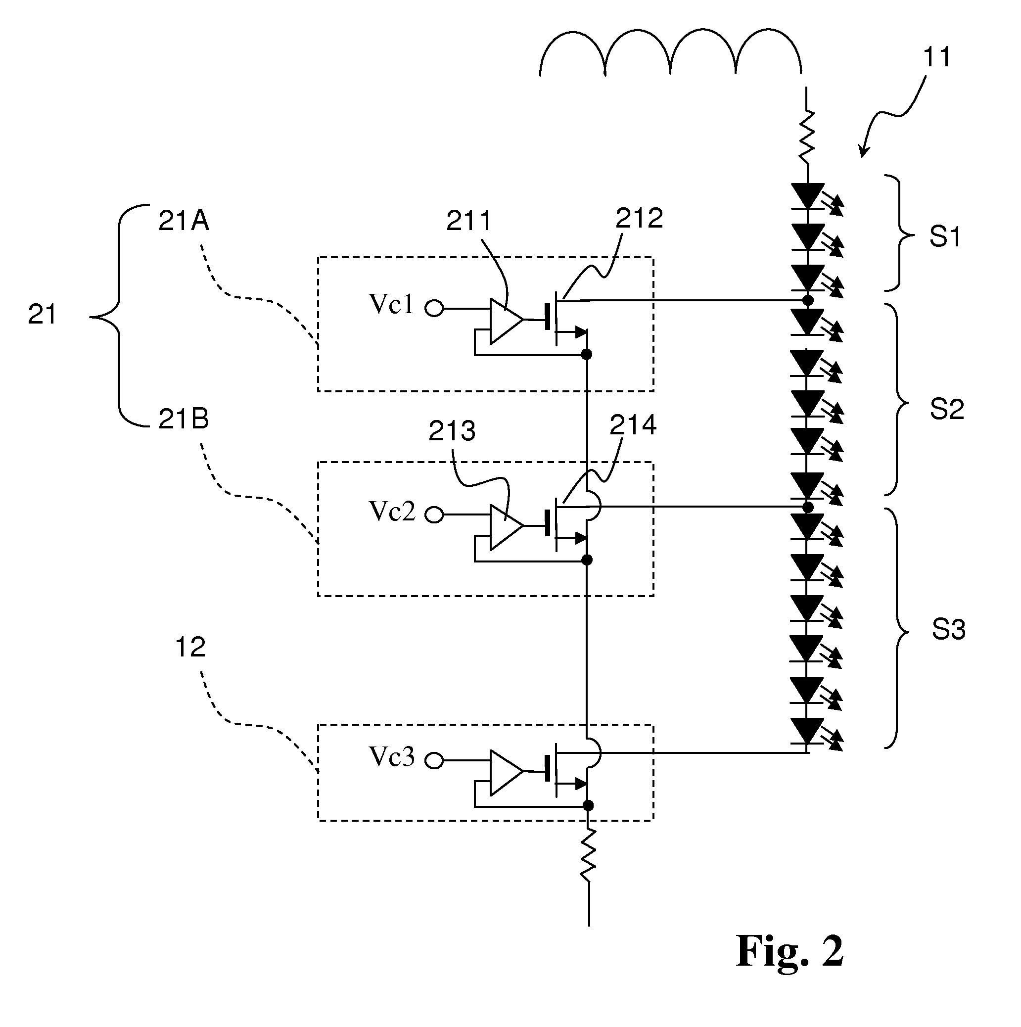
[0026]The LED selection circuit of the FIG. 2 uses the same circuit scheme as mentioned in FIG. 1, which further comprises at least one dividing current source (21) for dividing each of LED strings (11) into multiple segments (i.e. first, second and third segment (S1, S2, S3)) respectively. In this embodiment the dividing current source (21) comprises, but is not limited to, a first dividing current source (21A) and a second dividing current source (21B). The first dividing current source (21A) is connected to the LED string (11) and the current source (12), and comprises a first dividing error amplifier (211) and a first dividing transistor (212). The second dividing current source (21B) is connected to the first dividing current source (21A), the current source (12) and the LED string (11), and comprises a second dividing error amplifier (213) and a second dividing transistor (214).
[0027]The first dividing error amplifier (211) comprises a first input end, a second input end and an o
fourth embodiment
[0039]With reference to FIG. 4, an LED selection circuit that allows for switching the LED strings turning ON and OFF between 120 VAC and 240 VAC operation of an LED driver using the same circuit scheme as mentioned in FIGS. 1, 3A and 3B. The difference between the embodiments in FIGS. 3 and 4 is that the embodiment of the LED selection circuit shown in FIG. 4 does not use of the resistor divider network to sense a peak input AC voltage, and the PMOS module (30), the first NMOS transistor (N1) and the second NMOS transistor (N2) have been replaced with an NMOS module (40).
[0040]In this embodiment, the fourth LED string (11D) and the fifth LED string (11E) are connected in series as default. The controller (13) determines current passed through a first feedback resistor (Rf1) that indicates a desired current has been achieved when the fourth LED string (11D) and the fifth LED string (11E) are connected in series. If current passed through the first feedback resistor (Rf1) is not able to
PUM
 Abstract
Description
Claims
Application Information
 - R&D Engineer
- R&D Manager
- IP Professional
- Industry Leading Data Capabilities
- Powerful AI technology
- Patent DNA Extraction
Browse by: Latest US Patents, China's latest patents, Technical Efficacy Thesaurus, Application Domain, Technology Topic.
© 2024 PatSnap. All rights reserved.Legal|Privacy policy|Modern Slavery Act Transparency Statement|Sitemap