Sanitary ware of environmental protection type
a technology of environmental protection and sanitary ware, which is applied in the field of sanitary ware, can solve the problems of waste of water resources, easy dumping of sewage on the surface of the toilet bowl, and splashing, and achieve the effect of convenient maintenan
- Summary
- Abstract
- Description
- Claims
- Application Information
AI Technical Summary
Benefits of technology
Problems solved by technology
Method used
Image

Examples
embodiment 1
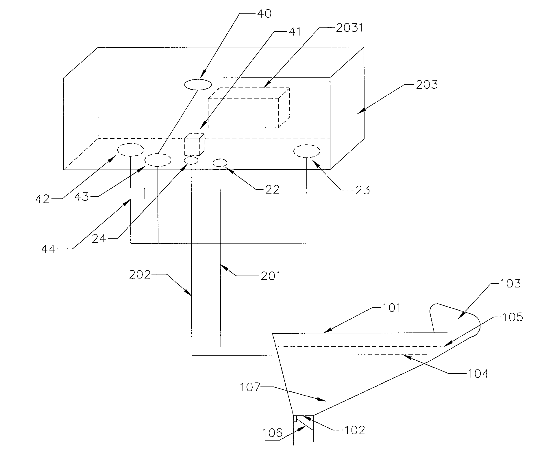
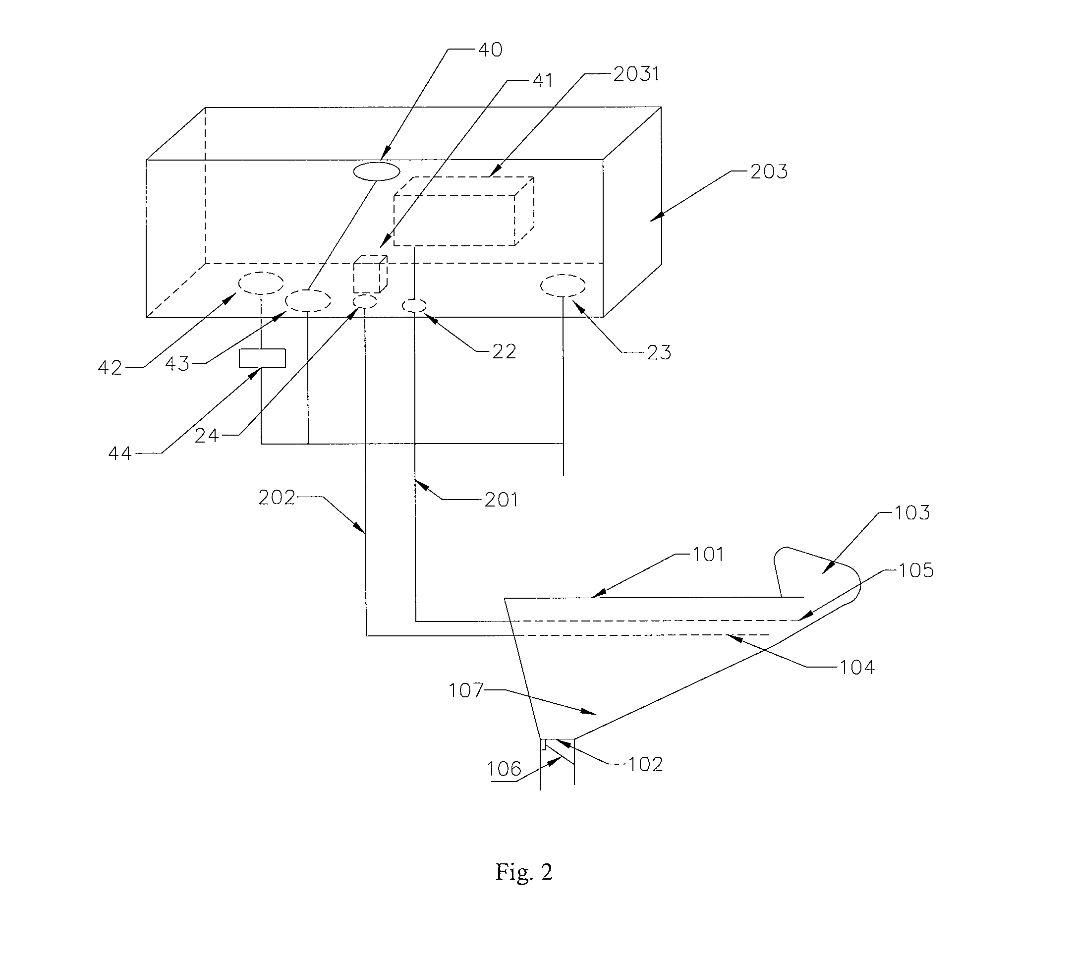
[0034]Referring to FIGS. 1 to 8, a dual-pipe foam and water flushing sanitary ware mainly comprises a sanitary ware body 101, a water tank 203, a foam pipe 201 and a water supplying pipe 202. The sanitary ware body 101 is provided with a sewage cavity 107 on its bottom, and the bottom of the sewage cavity 107 is provided with a sewage draining exit 102. Inside the sanitary ware body 101, a liquid channel 104 and a foam channel 105 are provided separately without communicating with each other. The sanitary ware 101 is further provided with a water inlet 1042 and a foam inlet 1052, the water inlet 1042 is in communication with the liquid channel 104, the foam inlet 1052 is in communication with the foam channel 105. The liquid channel 104 is provided with liquid outlets 1041, while the foam channel 105 is provided with foam outlets 1051, and the liquid outlets 1041 and the foam outlets 1051 are arranged on the upper inner wall of the sewage cavity 107. In this embodiment, the liquid chan
embodiment 2
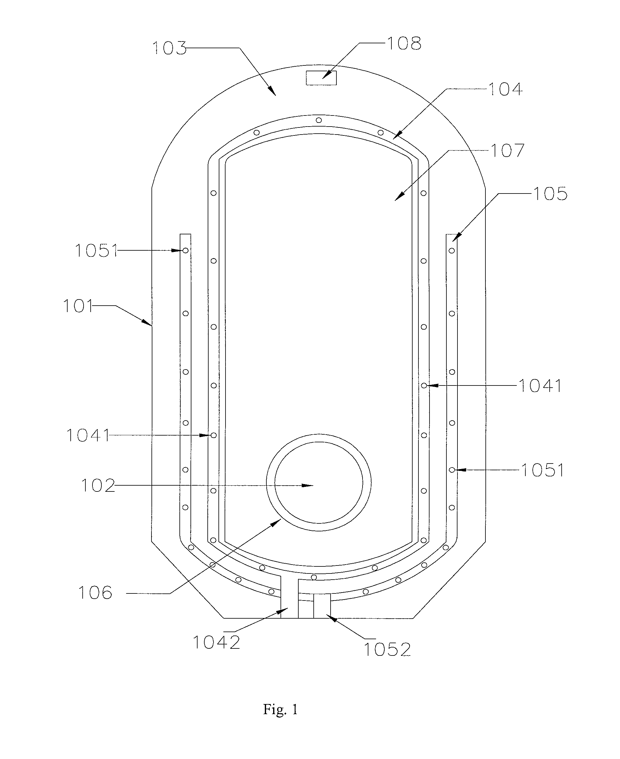
[0049]Referring to FIGS. 1 to 4, a structure of a dual-pipe foam and water flushing type squatting pan utilizing the above structure is schematically illustrated.
[0050]The squatting pan comprises a sanitary ware body 101, a water tank 203, a foam pipe 201 and a water supplying pipe 202. The sanitary ware body 101 is provided with a sewage cavity 107 on its bottom. The bottom of the sewage cavity 107 has a sewage draining exit 102 at one end, and a head portion 103 at the opposite end. A liquid channel 104 and a foam channel 105 are provided inside the sanitary ware body 101. The liquid channel 104 has liquid outlets 1041, and the foam channel 105 has foam outlets 1051. In this embodiment, the liquid channel 104 and the foam channel 105 are arranged in a manner surrounding the periphery of the sanitary ware body 101. A water inlet 1042 and a foam inlet 1052 are arranged at the end of the sanitary ware body 101 where the sewage draining exit 102 is located. The water inlet 1042 and the f
embodiment 3
[0063]Referring to FIGS. 7 and 8, an automatic foam-flushing sitting w.c. pan using the structure in the Embodiment 1 is shown.
[0064]The sitting w.c. pan comprises a water tank 710, a sitting w.c. pan body 101, a liquid level sensor 712 in the water tank (not shown), a foaming unit 713 and a controller 714. The controller 714 is set at the rear bottom portion of the sitting w.c. pan.
[0065]As shown in FIG. 8, the foaming unit 713 comprises an air pump 8130, a liquid tank 8131 and a foaming tank 8132. The outlet end of the air pump 8130 is connected to a four-port valve such that one air outlet is changed into three.
[0066]In particular, the liquid tank 8131 is filled with 600m1 of foam liquid, the liquid tank has an inlet connected to the air pump 8130 via a first air transportation pipe 8133, and also has an outlet connected to the foam tank 8132 through the liquid pipe 8134 in which a check valve 8138 and an adjusting valve 8137 are arranged in sequence. The adjusting valve 8137 is use
PUM
 Abstract
Description
Claims
Application Information
 - R&D Engineer
- R&D Manager
- IP Professional
- Industry Leading Data Capabilities
- Powerful AI technology
- Patent DNA Extraction
Browse by: Latest US Patents, China's latest patents, Technical Efficacy Thesaurus, Application Domain, Technology Topic.
© 2024 PatSnap. All rights reserved.Legal|Privacy policy|Modern Slavery Act Transparency Statement|Sitemap