Device for detecting tool tip position of remote-controlled actuator

a technology of remote control actuator and device, which is applied in the direction of osteosynthesis devices, prosthesis, applications, etc., can solve the problems of difficult to accurately estimate the tip position, difficult to fit the marker directly to the tool, and elongated pipe sections, etc., to achieve good attitude stability and good attitude stability of the distal end member relative to the external for

Inactive Publication Date: 2012-06-07
NTN CORP
View PDF12 Cites 14 Cited by
  • Summary
  • Abstract
  • Description
  • Claims
  • Application Information

AI Technical Summary

Benefits of technology

The present design allows for changes made during operation without affecting its orientation when there are other forces acting upon them like gravity. This ensures stable positioning over time even if some things change their way around due to factors such as temperature variations. Additionally, use of a motor instead of a hydraulic system simplifies the structure while still providing precise control over angular displacement.

Problems solved by technology

This technical problem addressed in this patents describes various ways to improve measurement accuracies in prosthetic knee replacements or procedures involving replacing parts like humeral components due to factors including friction caused by the long term usage of tools and environmental conditions. Existing solutions involve attaching markers onto the surface of the prosthesis instead of just filling up space around them within the prosthectic sheathing material. These approaches require accurate placement of these markers along the entire rod path of the instrument being worked towards the target area.

Method used


Image

  • Device for detecting tool tip position of remote-controlled actuator
  • Device for detecting tool tip position of remote-controlled actuator
  • Device for detecting tool tip position of remote-controlled actuator

Examples


Embodiment Construction

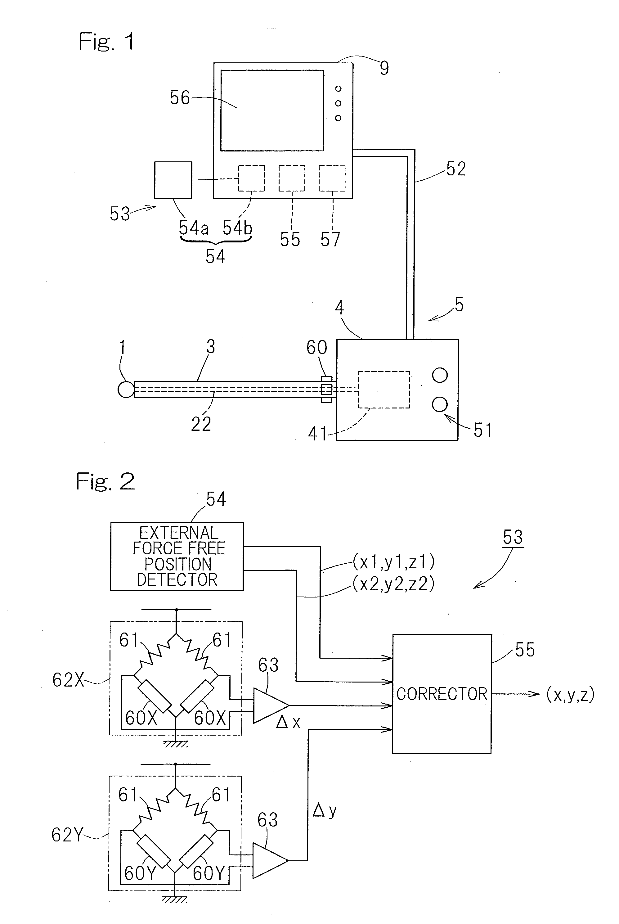
[0088]A first preferred embodiment of a remote controlled actuator provided with a tool tip position detecting device designed in accordance with the present invention is shown in FIG. 1. This remote controlled actuator, generally identified by 5, includes a main body housing 4, a spindle guide 3 of an elongated shape having a base end connected with the main body housing 4, and a tool 1 rotatably supported by a tip end of the spindle guide 3. A tool rotation drive source 41 is provided within the main body housing 4 and a rotation of the tool rotation drive source 41 is transmitted to the tool 1 through a drive transmission unit 22 inserted within the spindle guide 3. The tool rotation drive source 41 may, however, be provided outside the main body housing 4. The main body housing 4 is provided with the operator unit 51 for performing a switching on and off of the tool rotation drive source 41 and an adjusting operation of the rotational speed.

[0089]The main body housing 4 is connecte


PUM

PropertyMeasurementUnit
Flexibilityaaaaaaaaaa
Strain pointaaaaaaaaaa
Threshold limitaaaaaaaaaa

Abstract

Provided is a tool tip position detecting device (53) for a remote controlled actuator (5) having an elongated spindle guide (3), a tool (1) fitted to a tip thereof and a main body housing (4) having a base end of the spindle guide (3) connected thereto. The device (53) includes an external force free position detector (54) for detecting the tip position of the tool (1) from a detection value thereof, a strain detector (60) for detecting a strain of the spindle guide (3), and a corrector (55) for correcting the tip position of the tool (1), which has been detected by the external force free position detector (54), with the use of a detected strain value of the strain detector (60).

Description


Claims


Application Information

Patent Timeline
Owner NTN CORP
Why Eureka
Try Eureka