Anti-theft hand tool rack

Active Publication Date: 2013-05-23
SH JEN JI
View PDF1 Cites 7 Cited by
  • Summary
  • Abstract
  • Description
  • Claims
  • Application Information

AI Technical Summary

Benefits of technology

[0004]The object of the present invention is to provide a hand tool rack with anti-theft and user-friendly functions. It comprises a main frame, a plurality of positioning members and at least a cover frame. The main frame includes two side panels and a mediate portion between the side panels. A hook trough and a lump are symmetrically designated on each side panel. One end of the positioning member allows a hand tool to recess and the other end is attached onto t

Problems solved by technology

However, a disadvantage of the prior art exists.
Once the locking portions are cut off, the connection member is no longer able to be attached back onto the main fr

Method used


Image

  • Anti-theft hand tool rack
  • Anti-theft hand tool rack
  • Anti-theft hand tool rack

Examples


Embodiment Construction

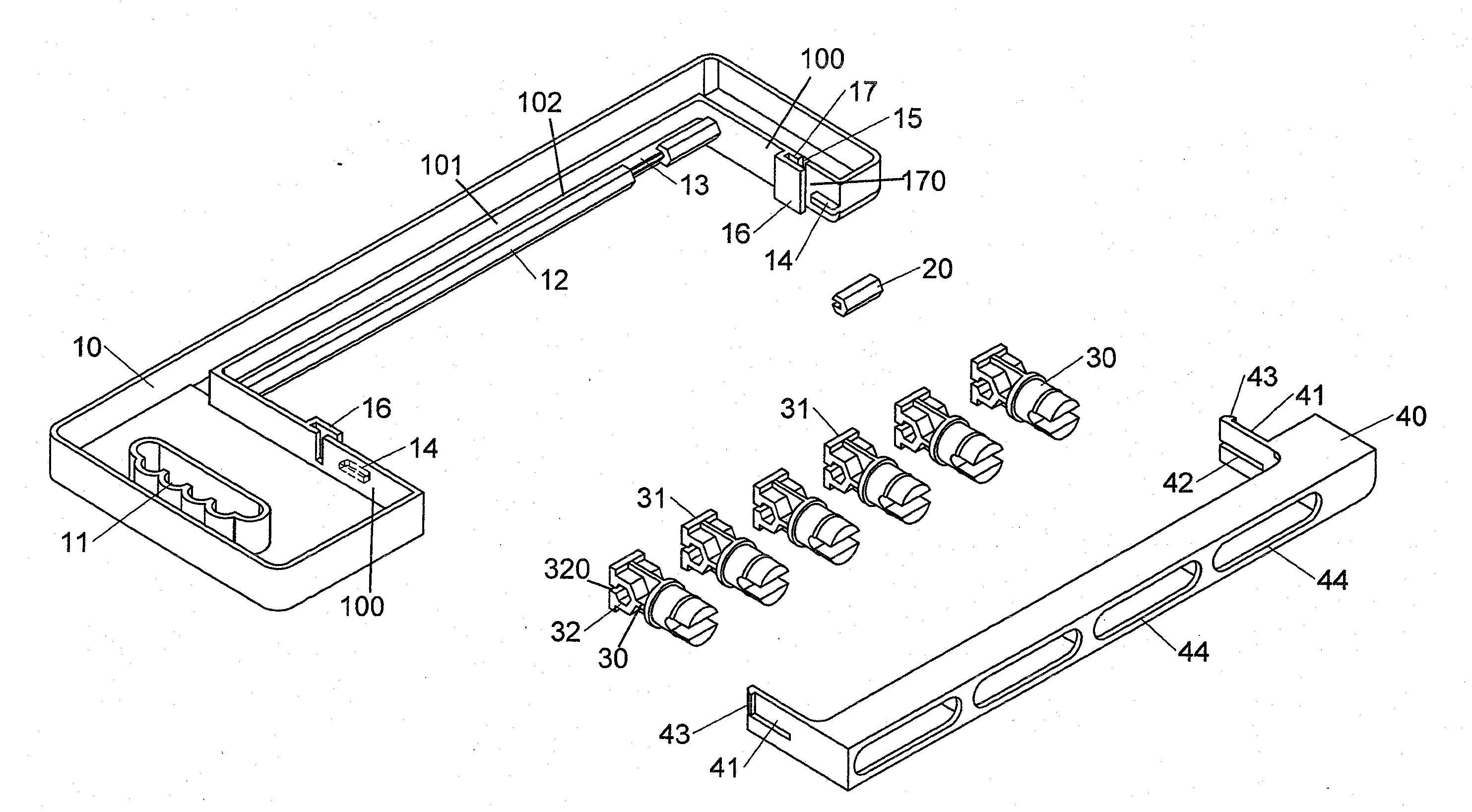
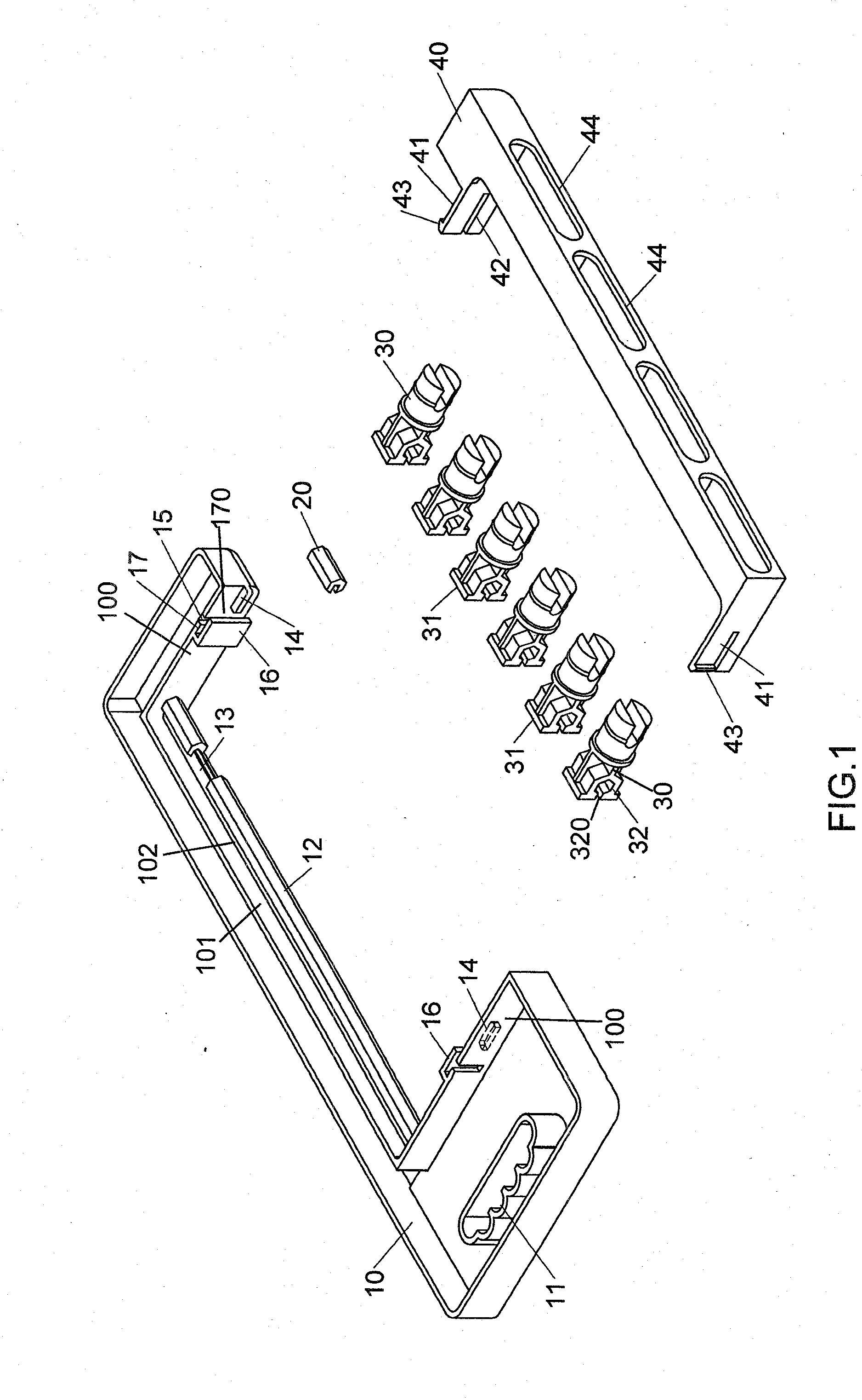
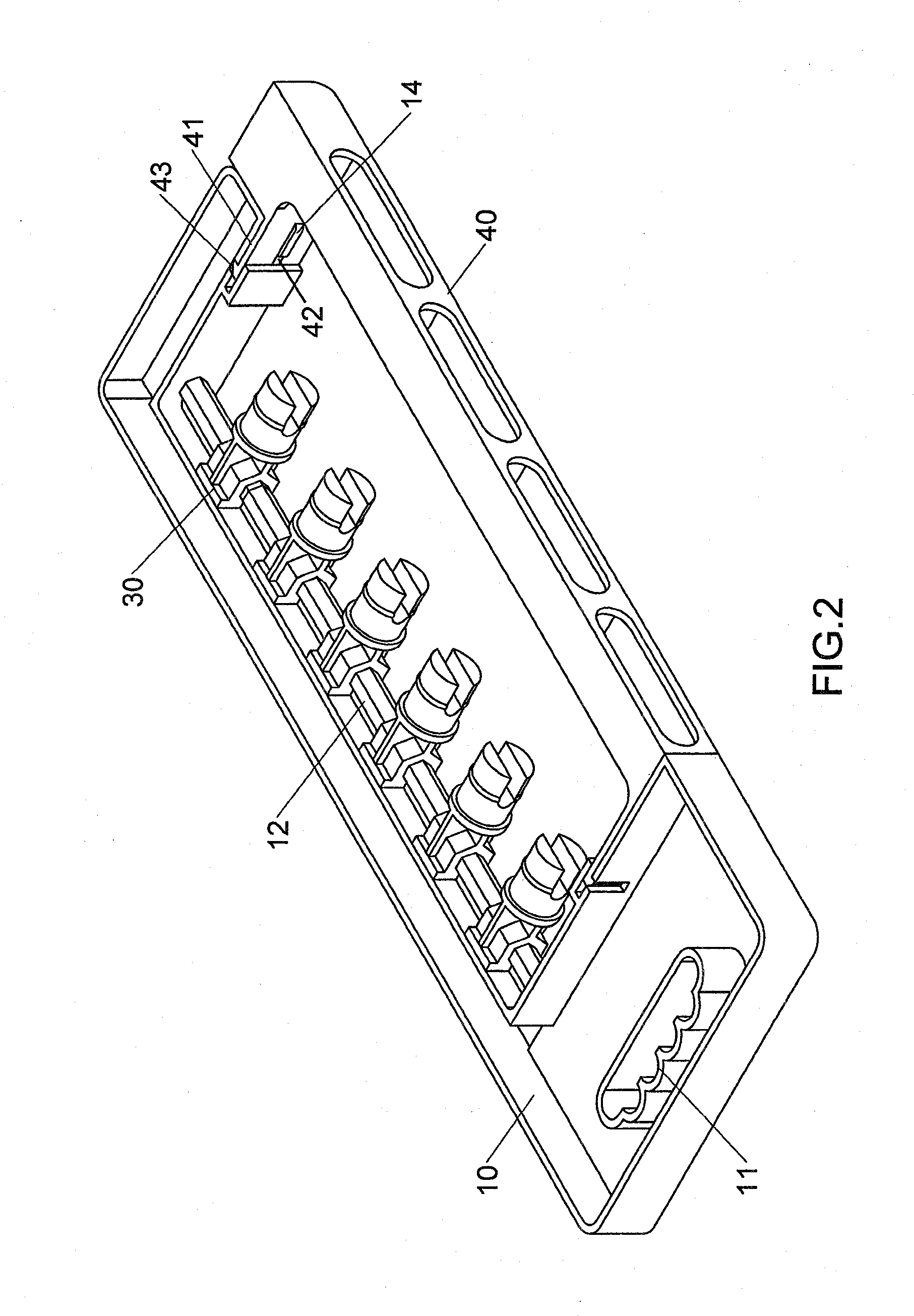
[0017]Referring to FIGS. 1 to 2, the hand tool rack of the present invention comprises a main frame 10, a plurality of positioning members 30 and at least a strip of cover frame 40. The mechanism of the hand tool rack is detailed as following.

[0018]The main frame 10 is a one-piece molded plastic whose one end has a hollow portion as its hand grip 11 for holding or hanging. A pair of side panels 100 is laterally extended in parallel beneath the hand grip 11, and a mediate portion 101 is longitudinally extended between the side panels 100. A first hook trough 15 and a lump 14 are symmetrically designated on each side panel 100. A longitudinal strip panel 102 is attached to the inner side of the mediate portion 101, and the other longitudinal side of the strip panel 102 is joined to a polygonal guide rail 12. The guide rail 12 is disconnected by a rail gap 13 which allows a rail filling 20 to lodge in for the guide rail 12 to form a complete polygon. A locking piece 16 is also symmetrical


PUM


Abstract

The present invention discloses a hand tool rack comprising main frame, positioning members and cover frame. The main frame includes two side panels and a mediate portion between the side panels. Each side panel has hook trough and lump. The positioning members mount on the mediate portion and allow hand tool to position. The cover frame has two brace pieces, and each brace piece has hook and guiding slot. When the brace pieces are hooked with the side panels, each hook is clipped into the corresponding hook trough and each lump is lodged into the corresponding guiding slot. Therefore, the hand tool rack is ensured to be anti-theft and user-friendly.

Description


Claims


Application Information

Patent Timeline
Owner SH JEN JI
Why Eureka
Try Eureka