System for corrective spinal surgery and method of use

a spinal surgery and spinal cord technology, applied in the field of spinal cord corrective surgery and the system of use, can solve the problems of affecting the treatment effect, and affecting the treatment

Active Publication Date: 2015-05-21
K2M
View PDF4 Cites 16 Cited by
  • Summary
  • Abstract
  • Description
  • Claims
  • Application Information

AI Technical Summary

Benefits of technology

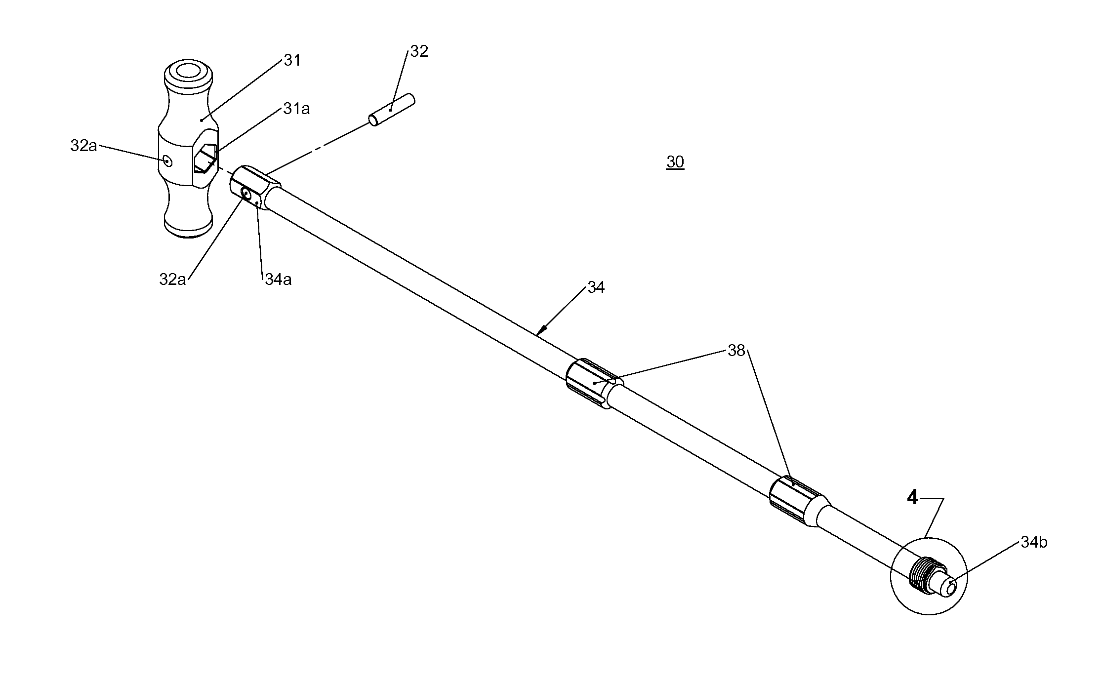
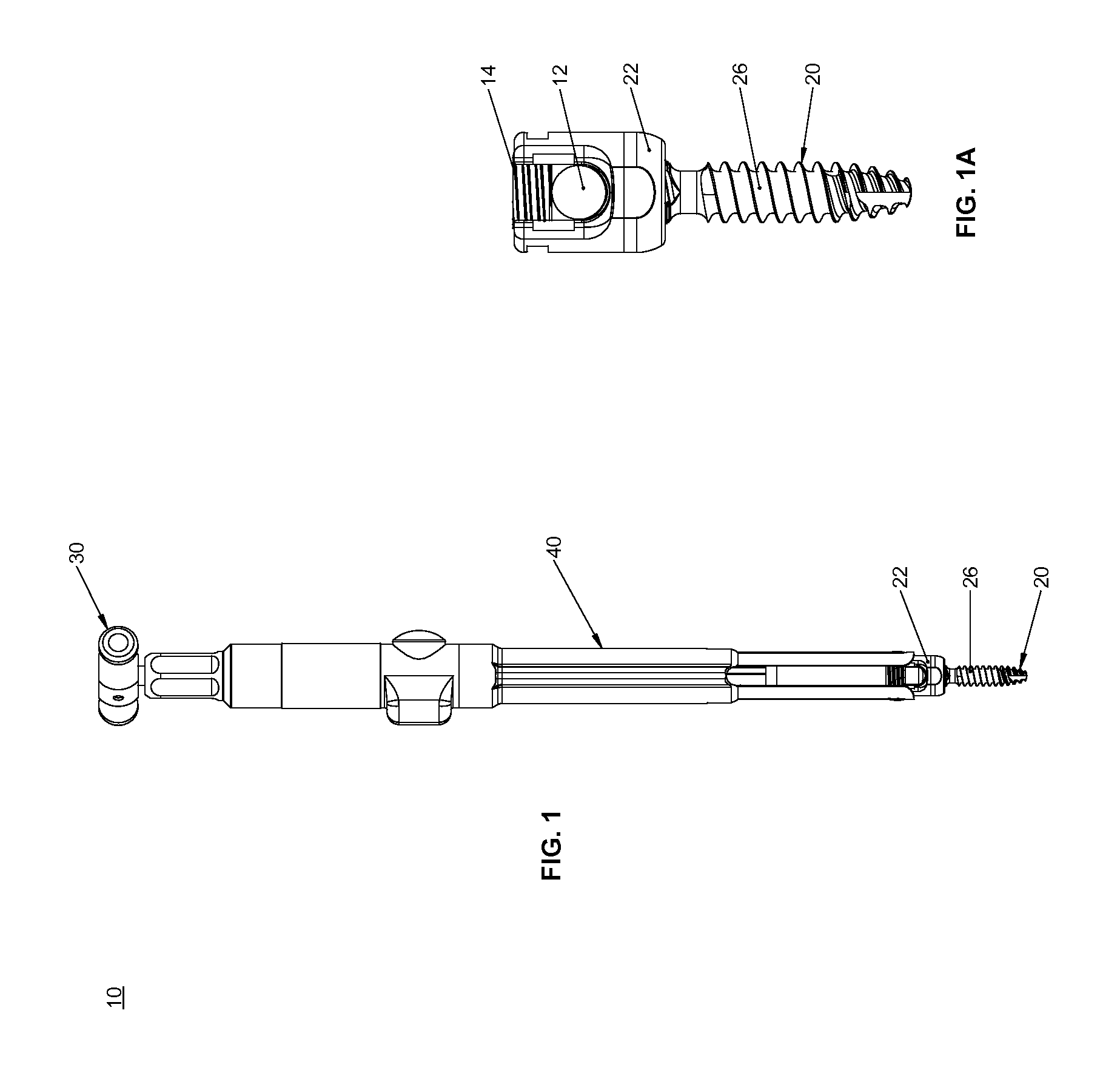
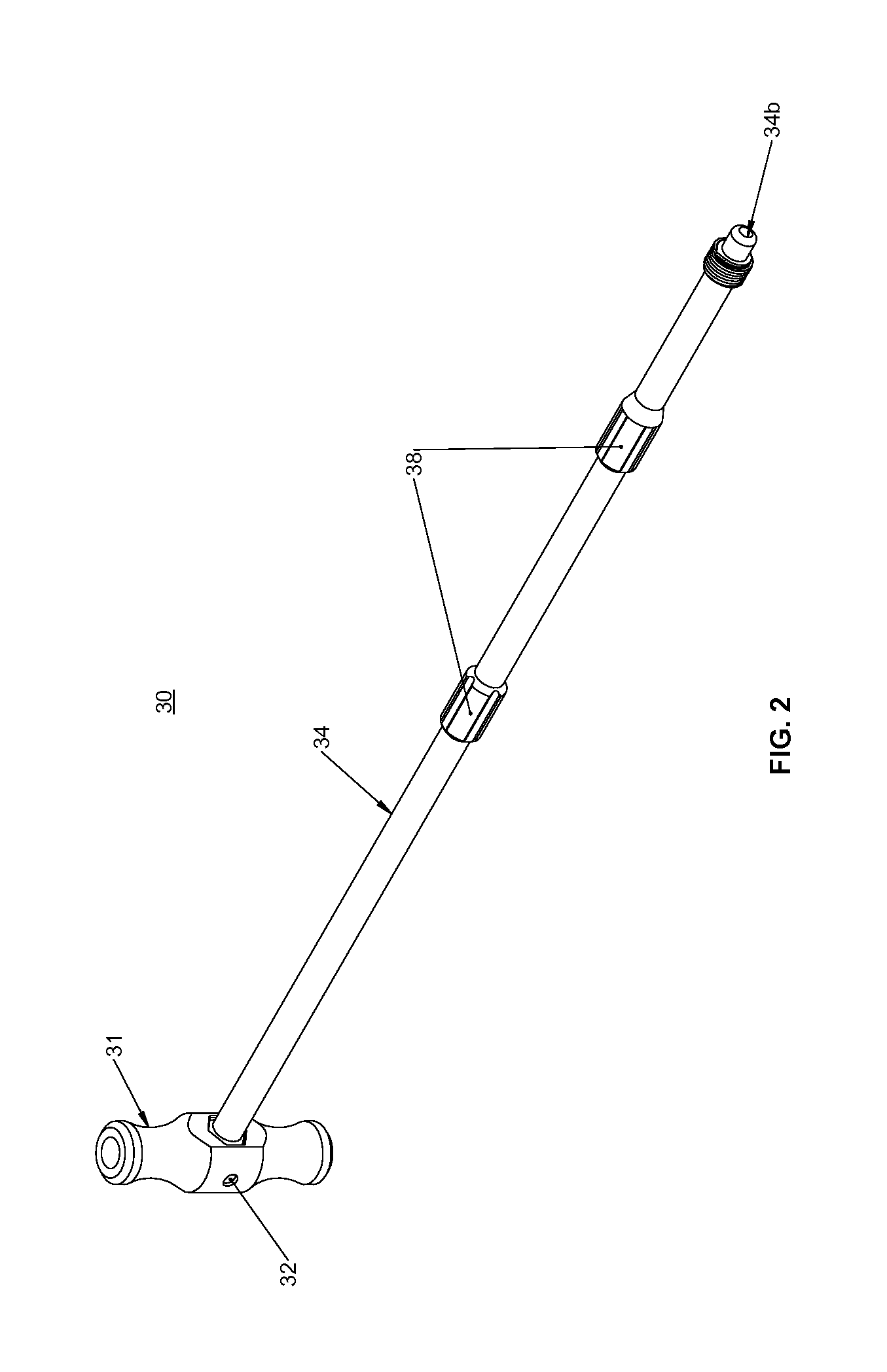
This patent describes a device called a pedicle screw locking system for connecting rods in a structure. It consists of a reducer tube and a locking driver. Inside the reducer tube there are two gears on its inside and a reduction sleeve around it. There also have fingers at the ends of these gears. These fingers fit into slots in the reduction sleeves, which hold them securely. When the reducer tube is connected to the rod, it moves along the rod's axis. Locking drivers connect to the reducer tube and move it backward when locked.

Problems solved by technology

This patent describes different methods used during medical surgeries to repair damaged parts of the spine. One method involves replacing all the affected area with artificial materials like plaster or fiberglass, creating space around it, then attaching them together using bolts or screws. Another method involves using prosthetic devices made of synthetic polymers like silicon rubber or polysulfonimide.

Method used


Image

  • System for corrective spinal surgery and method of use
  • System for corrective spinal surgery and method of use
  • System for corrective spinal surgery and method of use

Examples


Embodiment Construction

[0034]Embodiments of the present disclosure are now described in detail with reference to the drawings in which like reference numerals designate identical or corresponding elements in each of the several views. As used herein, the term “clinician” refers to a doctor, a nurse, or any other care provider and may include support personnel. Throughout this description, the term “proximal” will refer to the portion of the device or component thereof that is closer to the clinician and the term “distal” will refer to the portion of the device or component thereof that is farther from the clinician. In addition, the term “cephalad” is used in this application to indicate a direction toward a patient's head, whereas the term “caudad” indicates a direction toward the patient's feet. Further still, for the purposes of this application, the term “lateral” indicates a direction toward a side of the body of the patient, i.e., away from the middle of the body of the patient. The term “posterior” in


PUM


Abstract

A pedicle screw locking system includes a reduction tube and a locking driver. The reduction tube includes an inner shaft, a pair of grips, a reduction sleeve, and a rotatable tube. The inner shaft has a threaded end and reduction arms distally extending from the threaded end. Each grip of the pair of grips has a finger configured to engage the receiver of a pedicle screw. The reduction sleeve and the rotatable tube are disposed over and coaxially aligned with the inner shaft. The rotatable tube is coupled to the reduction sleeve. The rotatable tube moves the reduction sleeve relative to the reduction arms. The locking driver includes a threaded portion and a blunt tip. The threaded portion is configured to thread into threads in the receiver of the pedicle screw until the blunt tip locks the receiver of the pedicle screw.

Description


Claims


Application Information

Patent Timeline
Owner K2M
Why Eureka
Try Eureka