Fully balanced micro-machined inertial sensor

a micro-machined inertial sensor and fully balanced technology, applied in the direction of instruments, acceleration measurement using interia forces, devices using electric/magnetic means, etc., can solve the problem of adding material losses, causing load on the springs, and creating acoustic energy loss into the substra

Active Publication Date: 2016-03-24
RGT UNIV OF CALIFORNIA
View PDF22 Cites 36 Cited by
  • Summary
  • Abstract
  • Description
  • Claims
  • Application Information

AI Technical Summary

Benefits of technology

This patent describes improvements that include improved circuits and actuator systems for measuring linear acceleration caused by rotation about two axes. These improvements allow for accurate measurement of linear acceleration without requiring external devices like motors or other power sources.

Problems solved by technology

The technical problem discussed in this patent text relates to improving the quality of CMOS vibratory gyroscopes (VCMs) by reducing unwanted vibrations and interference friction. These issues include reduced sensitivity and increased quasitary phase noise, which limits the highest possible Q-value achieved. Additionally, the current tuning fork architecture has limitations in achieving optimal balance and preventing anchor losses.

Method used


Image

  • Fully balanced micro-machined inertial sensor
  • Fully balanced micro-machined inertial sensor
  • Fully balanced micro-machined inertial sensor

Examples


Embodiment Construction

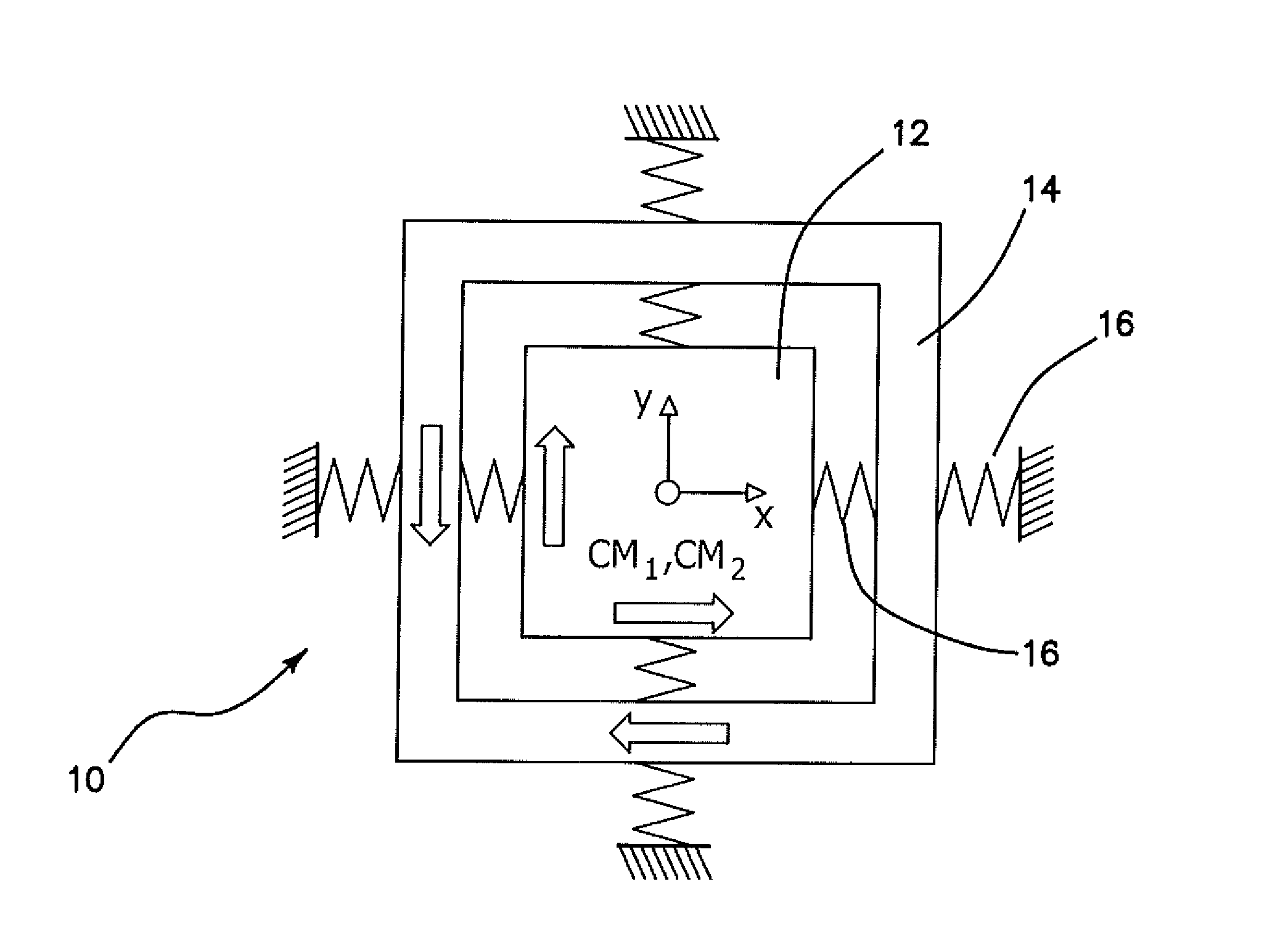
[0088]The illustrated embodiments disclose a balanced Coriolis vibratory gyroscope architecture that is force and torque balanced on both x and y modes. In contrast to tuning fork Coriolis Vibratory Gyroscopes, which are torque balanced only on one axis, this architecture is torque balanced on both axes (modes). As a result anchor losses are minimized not only on one but on two axes, which helps achieve high Q-factor on both modes of the Coriolis Vibratory Gyroscope.

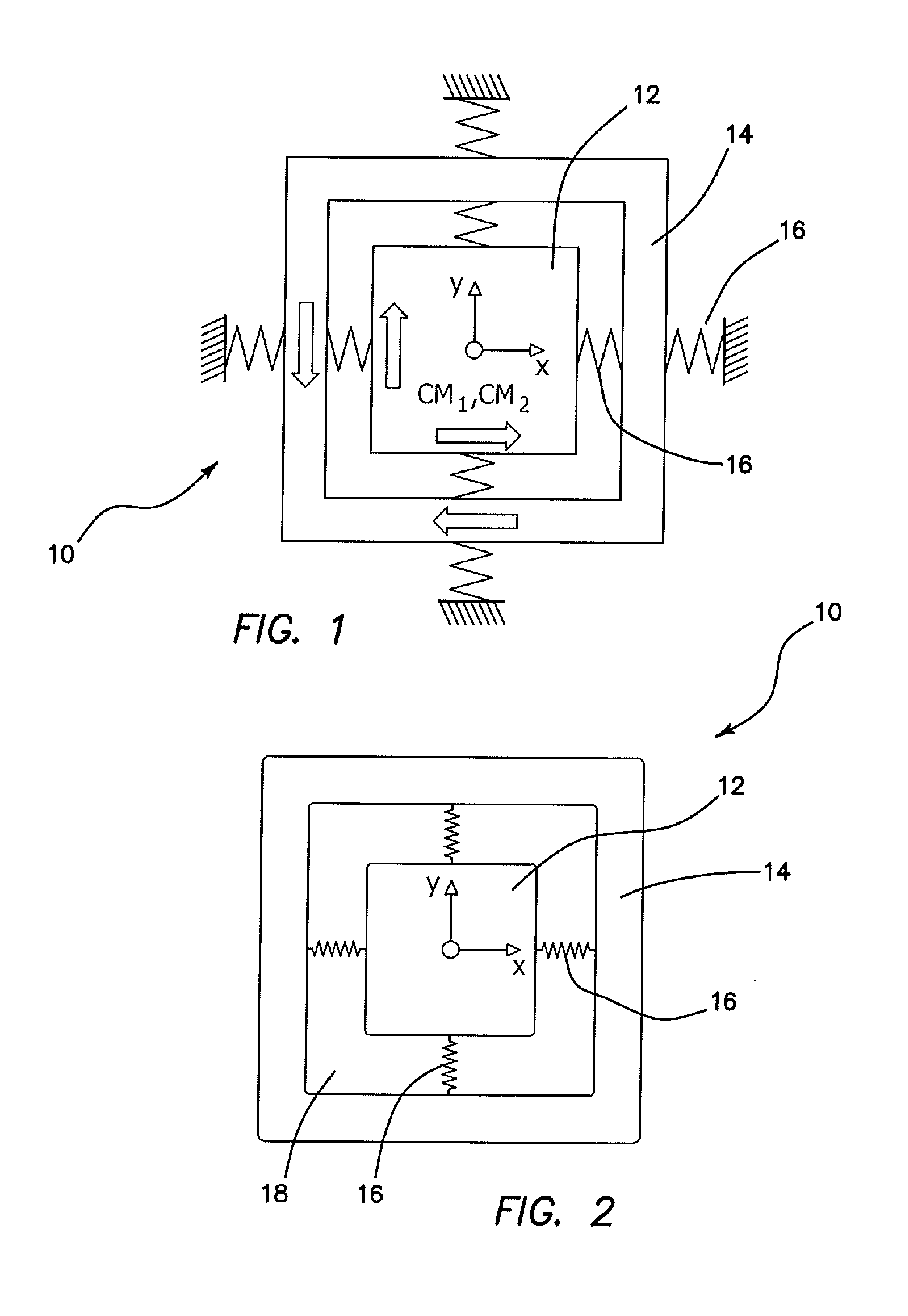
[0089]One implementation of such an architecture is a z-axis gyroscope 10 depicted in FIG. 1 where the gyroscope 10 is sensitive to rotation along the out-of-plane z axis. The gyroscope 10 is force and torque balanced as a result anchor losses are minimized not only one but two axes. Which helps achieve high Q-factor on both modes of the Coriolis Vibratory Gyroscope, diagrammatically depicted in FIG. 2. The gyroscopic mechanical element is comprised of two proof masses, a central tine 12 and a frame 14 around it. The frame


PUM


Abstract

The improvement includes an outer proof mass having a corresponding center of mass; and an inner proof mass having a corresponding center of mass, where the corresponding centers of mass of the outer proof mass and the inner proof mass are approximately co-located. Thus, a double Foucault pendulum is essentially provided in a micromachined gyroscope.

Description


Claims


Application Information

Patent Timeline
Owner RGT UNIV OF CALIFORNIA
Why Eureka
Try Eureka