Filtering system and hollow fiber membrane module for the same
a filtering system and hollow fiber membrane technology, applied in membrane technology, membrane technology, chemistry apparatus and processes, etc., can solve the problems of limiting the energy consumption of conventional pressurized-type hollow fiber membrane modules, limited permeation flux per unit time, etc., to prolong the life of the module and avoid the effect of reducing the filtration efficiency
- Summary
- Abstract
- Description
- Claims
- Application Information
AI Technical Summary
Benefits of technology
Problems solved by technology
Method used
Image

Examples
first embodiment
[0050]Hereinafter, referring to FIG. 4, the hollow fiber membrane module 200 according to the present invention will be described in detail.
[0051]As illustrated in FIG. 4, the hollow fiber membrane module 200 according to the first embodiment of the present invention comprises a case 210, a hollow fiber membrane 220 in the case 210, and first and second fixing members 231 and 232 dividing the inner space of the case 210 into an upper space S1, a filtration space S2, and a lower space S3.
[0052]The polymer that can be used for manufacturing the hollow fiber membrane 220 of the present invention comprises at least one of polysulfone, polyethersulfone, sulfonated polysulfone, polyvinylidene fluoride (PVDF), polyacrylonitrile, polyimide, polyamideimide resin, and polyesterimide.
[0053]The hollow fiber membrane 220 of the present invention may be a single-layer membrane or a composite membrane. If the hollow fiber membrane 220 is a composite membrane, it may comprise a tubular braid and a pol
second embodiment
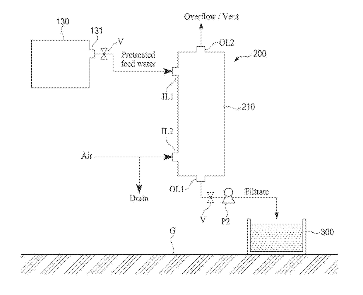
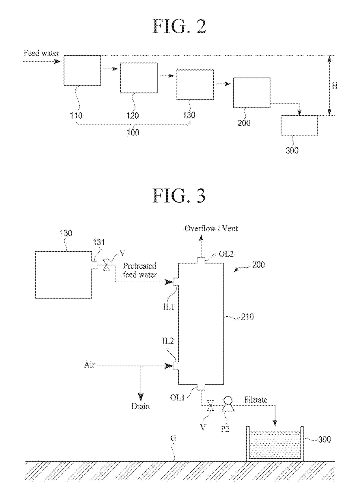
[0066]Hereinafter, referring to FIG. 5, the hollow fiber membrane module 200 according to the present invention will be explained.
[0067]Since the second embodiment is similar with the first embodiment described above, the difference between the first and second embodiments will be mainly explained.
[0068]As illustrated in FIG. 5, the second embodiment of the present invention is different from the first embodiment with respect to the positions of the first and second fixing members 231 and 232 within the case 210 and the positions of first and second inlets IL1 and IL2 on the case 210.
[0069]That is, according to the second embodiment of the present invention, the first fixing member 231 is disposed in the tubular body 211 at the upper open end, the second fixing member 232 is disposed in the tubular body 211 at the lower open end, the first inlet IL1 is formed on the upper part of the tubular body 211 so that the pretreated feed water can be introduced into the filtration space S2 betwe
third embodiment
[0077]Hereinafter, referring to FIG. 6, the hollow fiber membrane module 200 according to the present invention will be explained.
[0078]As illustrated in FIG. 6, the hollow fiber membrane module 200 according to the third embodiment of the present invention comprises: a case 210 having first to fourth spaces S1, S2, S3-1, and S3-2 sequentially arranged therein; a first fixing member 231 between the first and second spaces S1 and S2, the first fixing member 231 having a plurality of holes H through which the first and second spaces S1 and S2 are in fluid communication with each other; a second fixing member 232 between the second and third spaces S2 and S3-1; a third fixing member 233 between the third and fourth spaces S3-1 and S3-2; hollow fiber membranes 220 having first and second ends 221 and 222 potted in the first and second fixing members 231 and 232 respectively, the hollow fiber membranes 220 being in fluid communication with the third space S3-1; and at least one tube 240 hav
PUM
 Abstract
Description
Claims
Application Information
 - R&D Engineer
- R&D Manager
- IP Professional
- Industry Leading Data Capabilities
- Powerful AI technology
- Patent DNA Extraction
Browse by: Latest US Patents, China's latest patents, Technical Efficacy Thesaurus, Application Domain, Technology Topic.
© 2024 PatSnap. All rights reserved.Legal|Privacy policy|Modern Slavery Act Transparency Statement|Sitemap