Electron microscope

a technology of electron microscope and electron microscope, which is applied in the field of electron microscope, can solve the problems of analyzing a base material immersed in a liquid environment, unable to achieve a resolution below 100 nm due to the optical wavelength, and observing a limitation of liquid or water-contained samples

Inactive Publication Date: 2017-09-14
TAIWAN ELECTRON MICROSCOPE INSTR CORP
View PDF4 Cites 0 Cited by
  • Summary
  • Abstract
  • Description
  • Claims
  • Application Information

AI Technical Summary

Benefits of technology

The present invention relates to an electron microscopy system for examining objects with high resolution images. It uses two charged particles to create an image of the object being observed. A special device called a charge-particle beam generator generates one charged particle beam while another device called a camera captures the other charged particle's image. This results in a clear image of the object being studied without any distortion or blurring caused by the air gap between them.

Problems solved by technology

The technical problem addressed by this patent is how to improve the accuracy and productivity of detecting liquids containing materials like silicone oil (SiO2) and other substances while also being able to monitor changes over time in these liquids without requiring expensive equipment.

Method used


Image

  • Electron microscope
  • Electron microscope
  • Electron microscope

Examples


Embodiment Construction

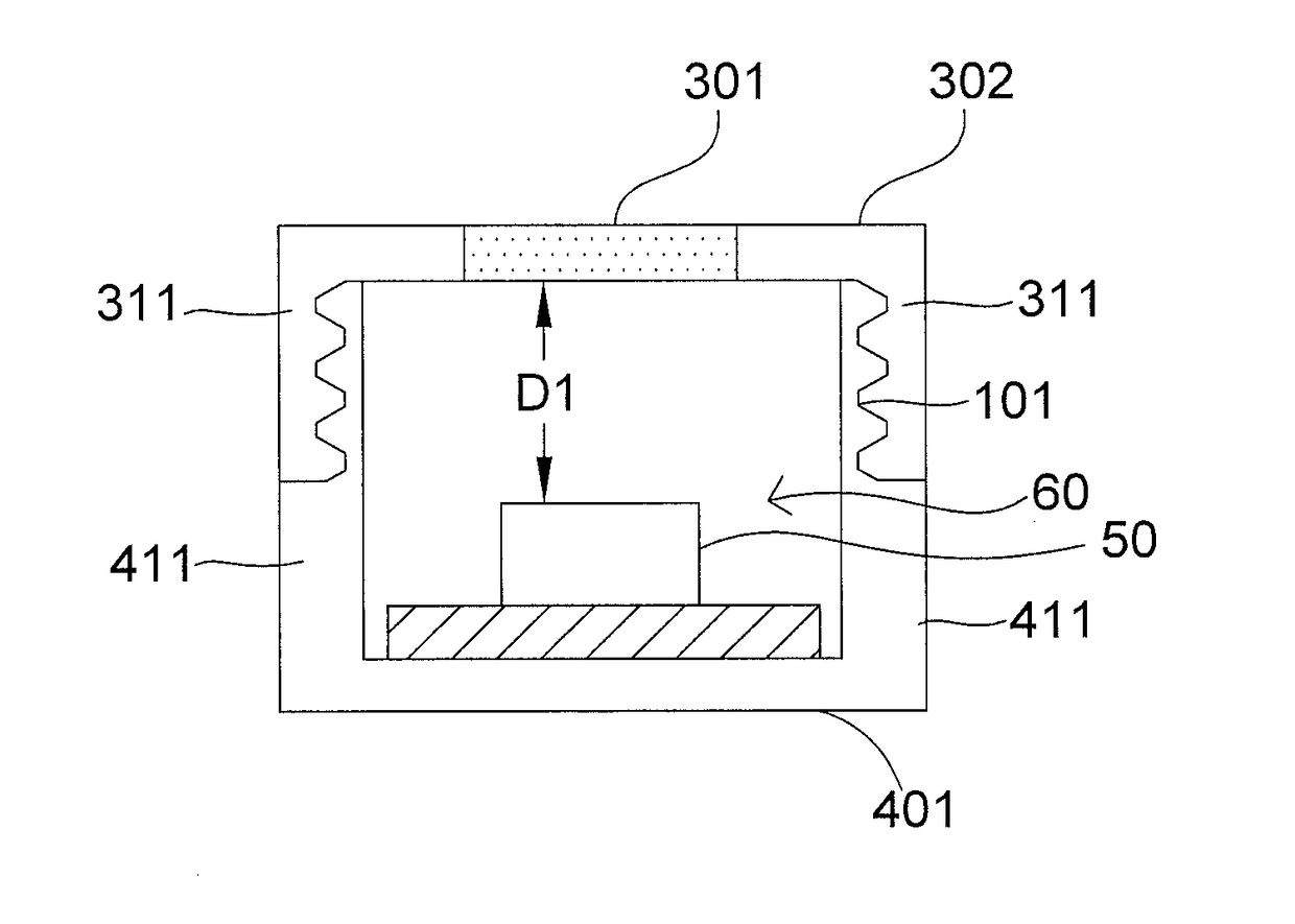
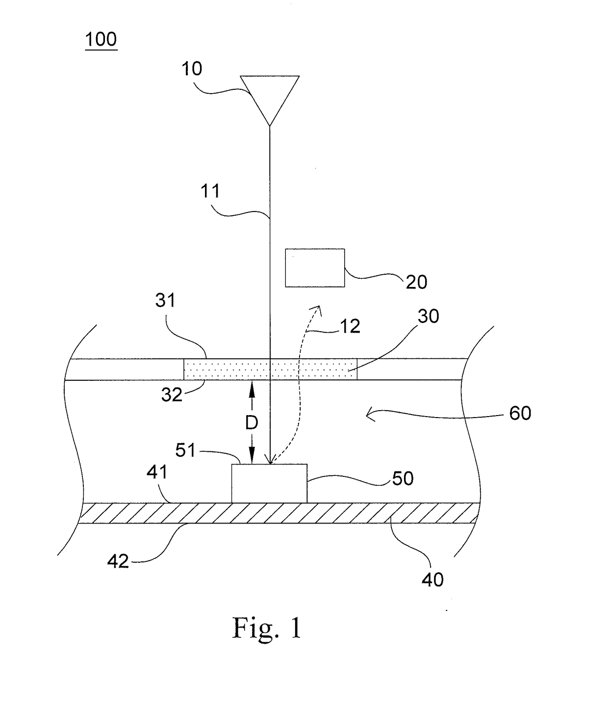
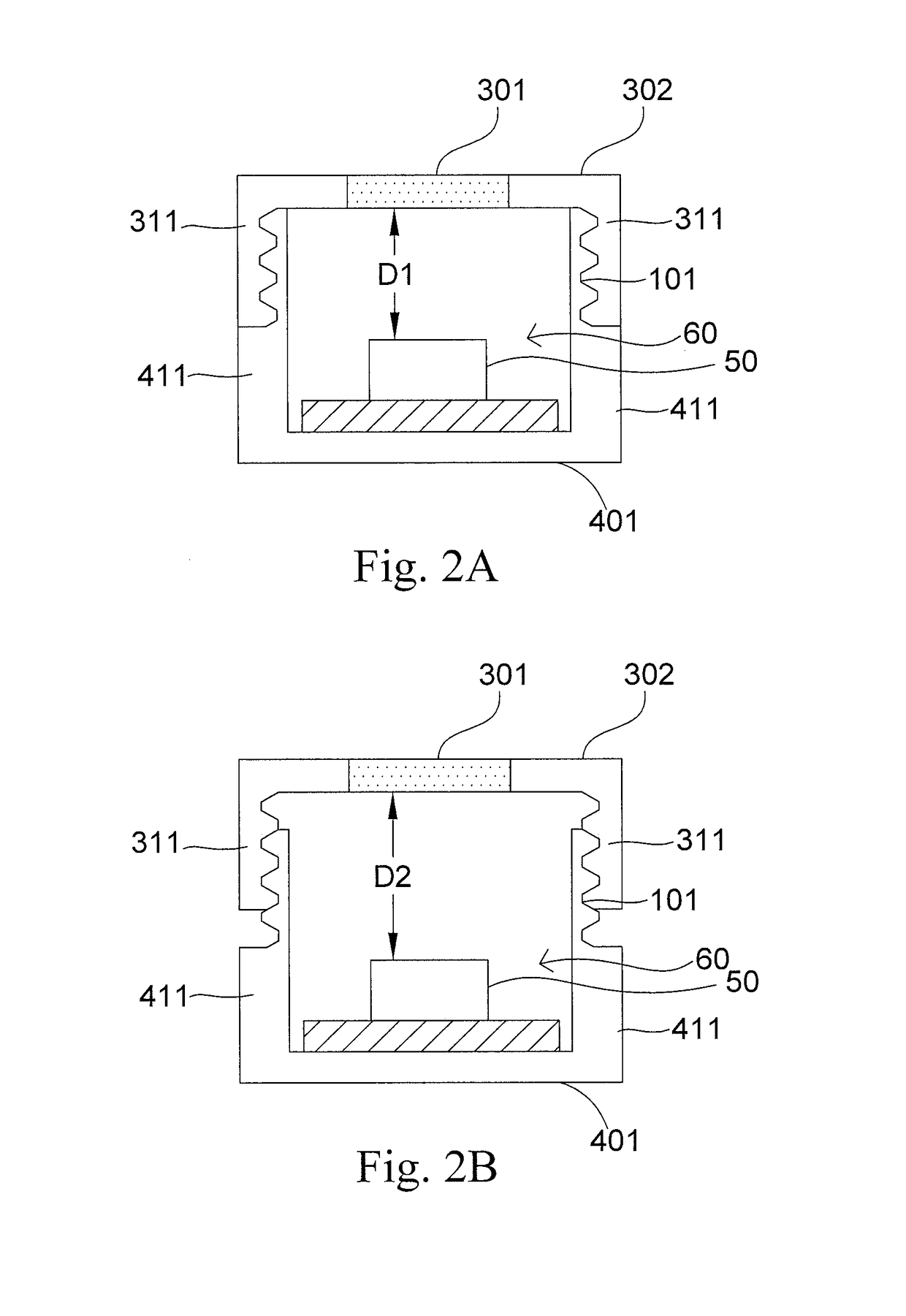
[0032]Various embodiments of the present invention will be described in detail below and illustrated in conjunction with the accompanying drawings. In addition to these detailed descriptions, the present invention can be widely implemented in other embodiments, and apparent alternations, modifications and equivalent changes of any mentioned embodiments are all included within the scope of the present invention and based on the scope of the Claims. In the descriptions of the specification, in order to make readers have a more complete understanding about the present invention, many specific details are provided; however, the present invention may be implemented without parts of or all the specific details. In addition, the well-known steps or elements are not described in detail, in order to avoid unnecessary limitations to the present invention. Same or similar elements in Figures will be indicated by same or similar reference numbers. It is noted that the Figures are schematic and may


PUM


Abstract

An electron microscope includes a charged particle beam generator, a detector, a film and a bearing unit. The charged particle beam generator generates a first charged particle beam to bomb an object. The detector detects a second charged particle from the object to form an image. The film disposes on downstream of charged particle beam generator and has a first surface and a second surface. A space between charged particle beam generator and the first surface of film is a vacuum environment. The bearing unit disposes at a side of second surface of film and has a bearing surface and a back surface. The object disposes on the bearing surface of the bearing unit and a distance between an analyzed surface of the object and the film is less than a predetermined spacing. A liquid space exists between the analyzed surface and the film to be filled a liquid.

Description


Claims


Application Information

Patent Timeline
Owner TAIWAN ELECTRON MICROSCOPE INSTR CORP
Why Eureka
Try Eureka