Hierarchical fault diagnosis and prognosis of a system

a system and fault technology, applied in the direction of engine starters, electrical control, instruments, etc., can solve the problems of affecting the performance of other subsystems, the state of health of the system as a whole, and the reported fault mode, so as to improve the efficiency and usefulness of system diagnostic and prognosis

Active Publication Date: 2018-10-25
GM GLOBAL TECH OPERATIONS LLC
View PDF0 Cites 5 Cited by
  • Summary
  • Abstract
  • Description
  • Claims
  • Application Information

AI Technical Summary

Benefits of technology

This patent describes a new way of analyzing systems that are being used for monitoring or managing their performance. It suggests identifying specific areas where problems occur in order to make better use of these systems. By doing this, it can improve efficiency and effectiveness compared to traditional methods.

Problems solved by technology

This patent describes how internal combustion engines can generate enough energy to turn on their starter motors. However, if some parts fail due to poor quality or damage caused by external factors like rainwater or snow, it could lead to a sudden loss of power supply that could result in a no-go or even a catastrophic shutdown. Therefore, this problem needs to be solved through careful monitoring and control over all components involved in the engine startup system.

Method used


Image

  • Hierarchical fault diagnosis and prognosis of a system
  • Hierarchical fault diagnosis and prognosis of a system
  • Hierarchical fault diagnosis and prognosis of a system

Examples


Embodiment Construction

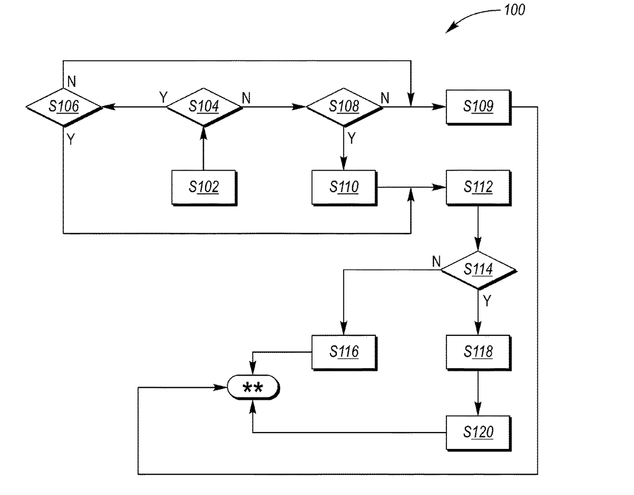
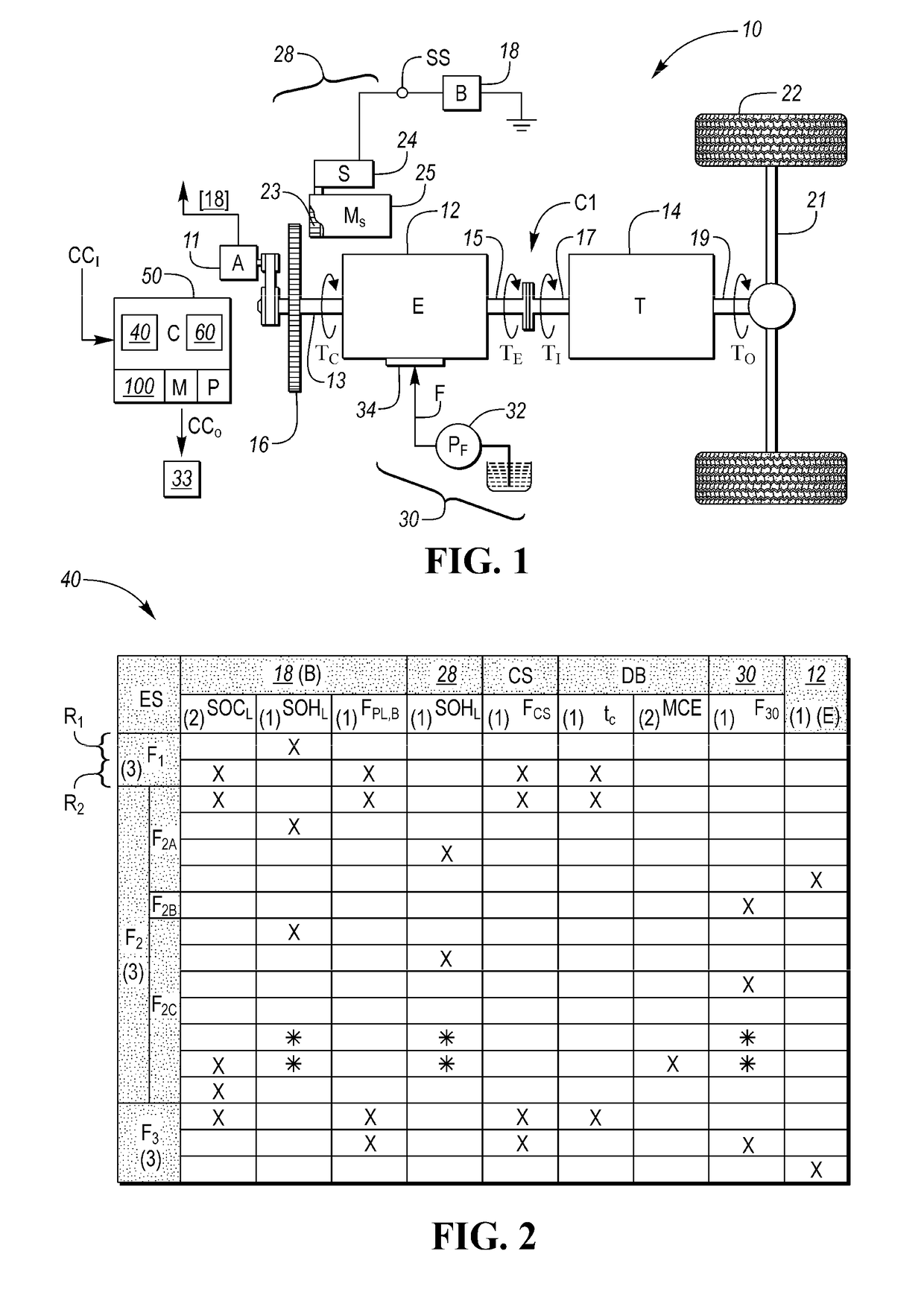
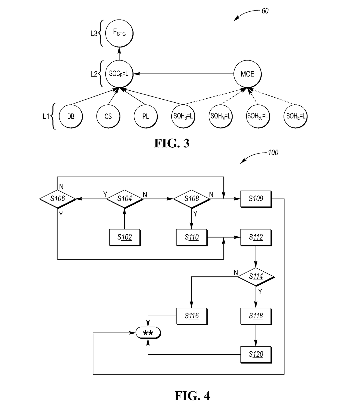
[0017]Referring to the drawings, wherein like reference numbers refer to like components, a vehicle 10 is depicted in FIG. 1 as a non-limiting example embodiment of a top-level system having multiple interrelated subsystems. The vehicle 10 is used hereinafter to illustrate a non-limiting type of system that lends itself to the beneficial use of a hierarchical and holistic diagnostic method 100, an example of which is depicted in FIG. 4 and explained below. The method 100 may also be readily applied to non-vehicular systems and subsystems other than those described herein. For illustrative clarity and consistency, the vehicle 10 of FIG. 1 will be described hereinafter in the context of an engine starting system 28 without limiting applications of the method 100 to systems in the form of the vehicle 10 or the engine starting system 28.

[0018]The vehicle 10 includes an internal combustion engine (E) 12 that is coupled to a transmission (T) 14, with the latter having internal gear sets, rot


PUM


Abstract

A method for diagnosing a fault mode in a system includes recording a hierarchical precedence rule assigning a priority level to fault modes of the system, and recording, in a fault report matrix, fault reports indicative of a corresponding one or more of the fault modes. The method also includes using the hierarchical precedence rule to determine the assigned relative priority level for the fault reports in response to a predetermined condition, e.g., a requested engine starting event, and identifying a root cause subsystem as a subsystem having the highest assigned priority level. A control action executed via the controller identifies the root cause subsystem by recording a diagnostic code and/or transmitting a message. The system is also disclosed, as is a computer-readable medium programmed with instructions embodying the method.

Description


Claims


Application Information

Patent Timeline
Owner GM GLOBAL TECH OPERATIONS LLC
Why Eureka
Try Eureka