Method and system to detect r-waves in cardiac activity signals

a cardiac activity and signal detection technology, applied in the field of implantable medical devices, can solve the problems of sudden changes in the amplitude of egm, limited impulsive propagation through the av node, and false positive af detections

Active Publication Date: 2019-12-19
PACESETTER INC
View PDF0 Cites 6 Cited by
  • Summary
  • Abstract
  • Description
  • Claims
  • Application Information

AI Technical Summary

Benefits of technology

This patent describes a way to adjust the timing for processing data based on factors like speed or movement. By setting both times at different levels, the system can adaptively react accordingly.

Problems solved by technology

This patent describes various technical problem addressed in this patent relating to improving the accuracy of detecting R-waves in implanted cardiac pacemakers. Current methods involve analyzing the frequency characteristics of the AC waves captured by the implantable cardiac pacemaker, but they cannot accurately determine if specific patterns occur in the recorded waveform. Additionally, previous attempts to reduce interference caused by the presence of high-frequency components in the recorded waveforms resulted in errors in identifying and calculating the minimum sensing gap required for triggering therapy.

Method used


Image

  • Method and system to detect r-waves in cardiac activity signals
  • Method and system to detect r-waves in cardiac activity signals
  • Method and system to detect r-waves in cardiac activity signals

Examples


Embodiment Construction

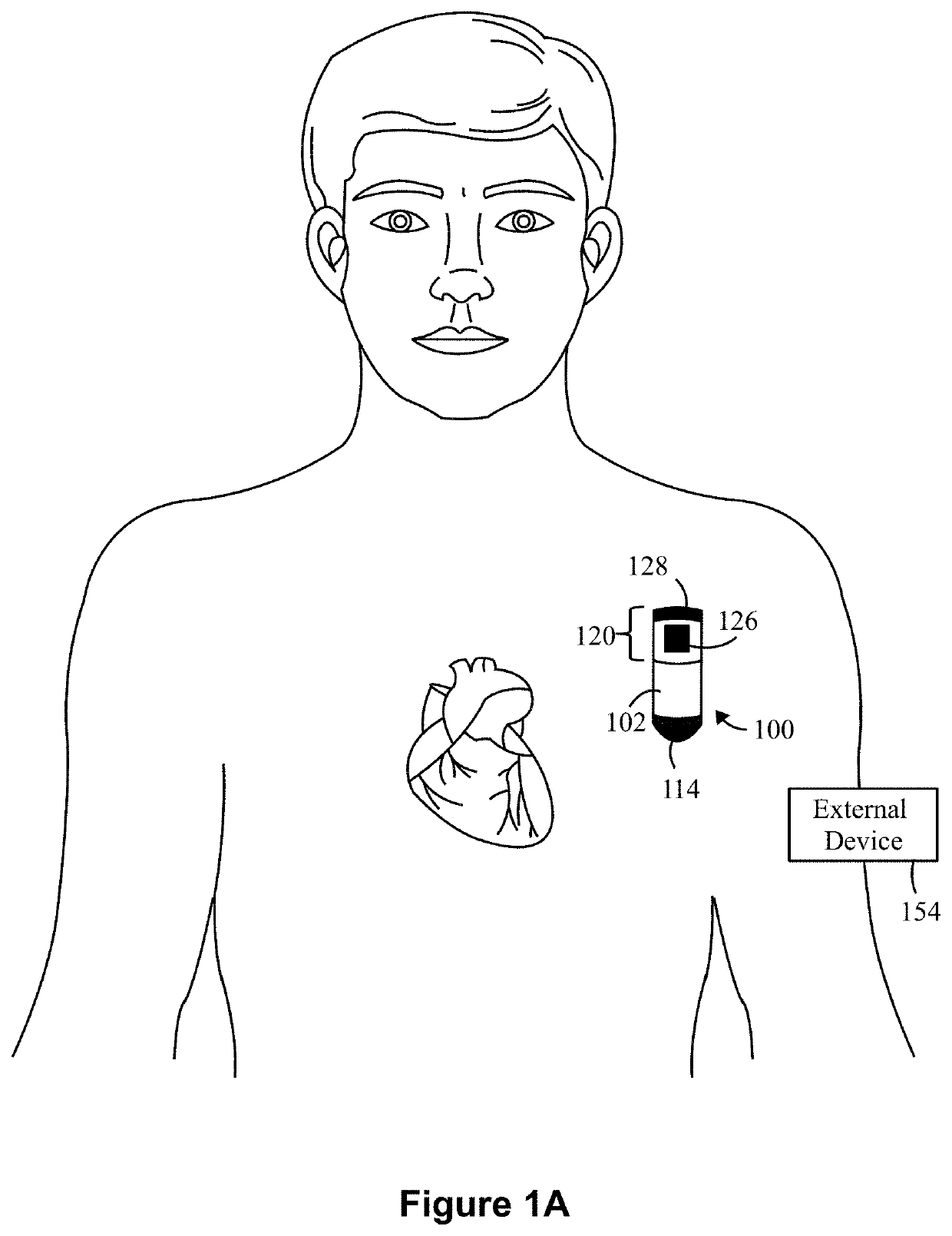
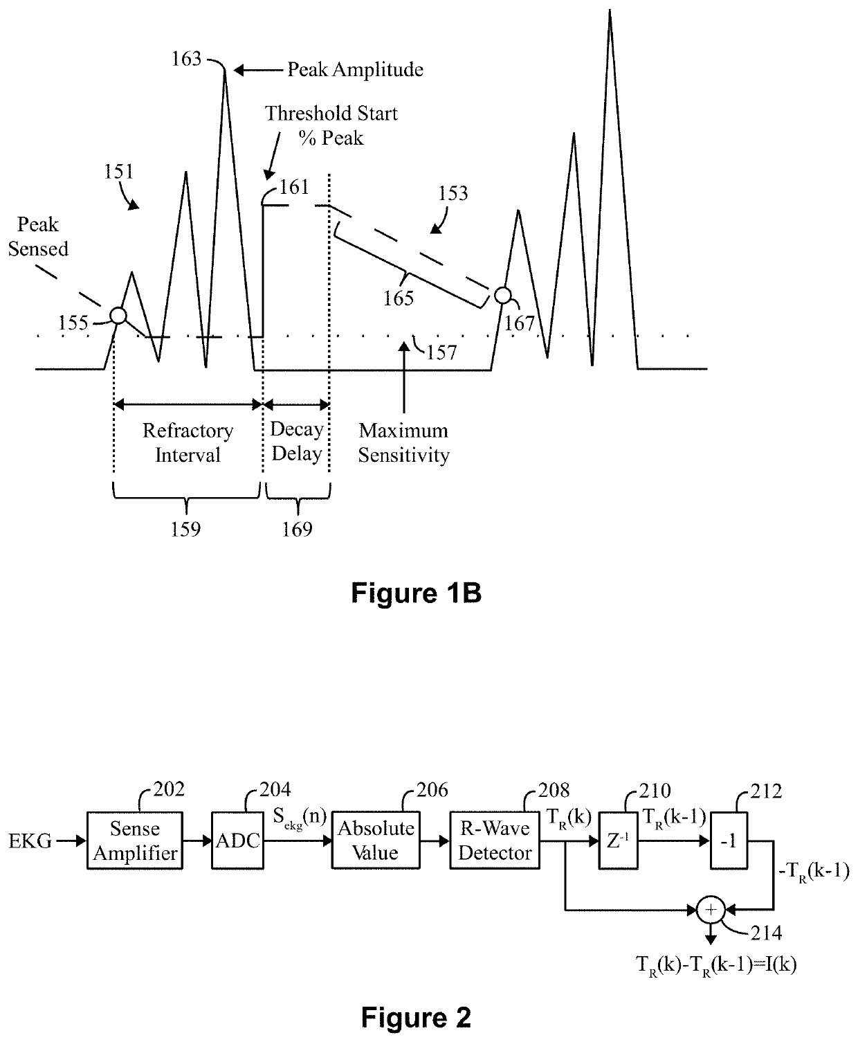
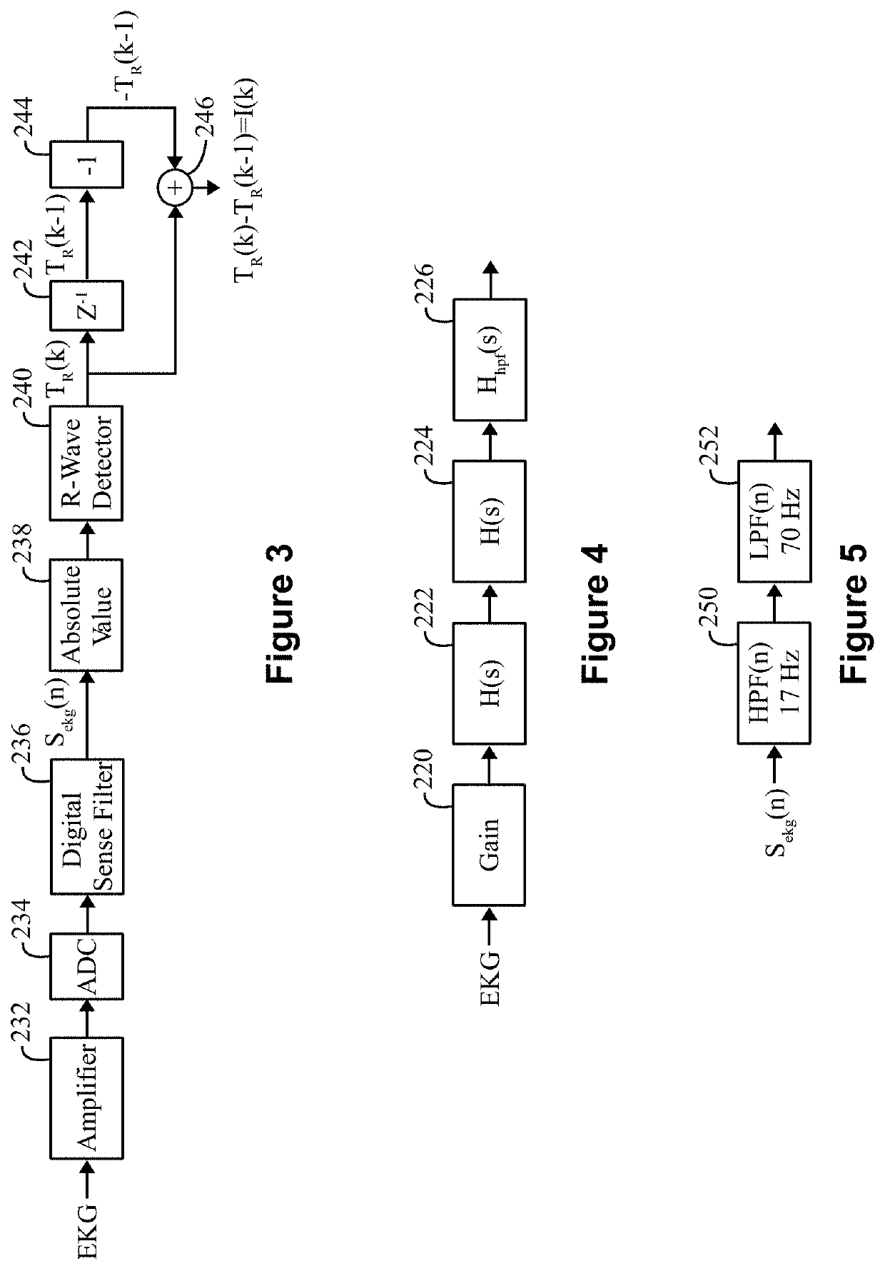
[0040]The terms “cardiac activity signal”, “cardiac activity signals”, “CA signal” and “CA signals” (collectively “CA signals”) are used interchangeably throughout to refer to an analog or digital electrical signal recorded by two or more electrodes positioned subcutaneous or cutaneous, where the electrical signals are indicative of cardiac electrical activity. The cardiac activity may be normal / healthy or abnormal / arrhythmic. Non-limiting examples of CA signals include ECG signals collected by cutaneous electrodes, and EGM signals collected by subcutaneous electrodes.

[0041]The terms “beat” and “cardiac event” are used interchangeably and refer to both normal or abnormal events.

[0042]The terms “normal” and “sinus” are used to refer to events, features, and characteristics of, or appropriate to, a heart's healthy or normal functioning.

[0043]The terms “abnormal,” or “arrhythmic” are used to refer to events, features, and characteristics of, or appropriate to, an un-healthy or abnorma


PUM


Abstract

A computer Implemented method and system for detecting arrhythmias in cardiac activity are provided. The method is under control of one or more processors configured with specific executable instructions. The method obtains far field cardiac activity (CA) signals and applies a direction related responsiveness (DRR) filter to the CA signals to produce DRR filtered signals. The method compares a current sample from the CA signals to a prior sample from the DRR filtered signals to identify a direction characteristic of the CA signals and defines the DRR filter based on a timing constant that is set based on the direction characteristic identified. The method analyzes the CA signals in connection with the DRR filtered signals to identify a peak characteristic of the CA signals and determines peak to peak intervals between successive peak characteristic. The method detects at least one of noise or an arrhythmia based on the peak to peak intervals and records results of the detecting.

Description


Claims


Application Information

Patent Timeline
Owner PACESETTER INC
Why Eureka
Try Eureka