Street Sweeper
- Summary
- Abstract
- Description
- Claims
- Application Information
AI Technical Summary
Benefits of technology
Problems solved by technology
Method used
Image

Examples
first embodiment
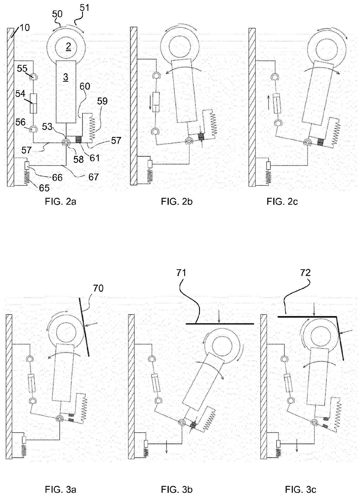
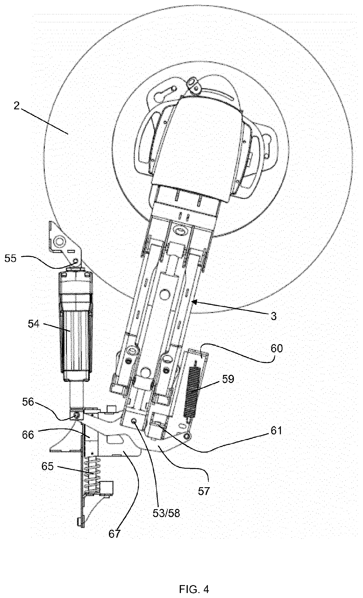
[0070]A first aspect of the invention relates to a mechanism which allows for controlling the position of the brushes 2 in the horizontal plane. The mechanism is also capable of absorbing shocks in the case of the presence of obstacles exerting an external force in one or more directions. FIGS. 2a-2c show, conceptually, the operation of the mechanism according to a FIG. 2a shows a top view of the right-hand side brush 2 of the sweeper. The mechanism which operates the left-hand side brush is symmetrical to the right-hand side mechanism. The brush 2 rotates in a direction 50. When the brush is in contact with the ground, its rotation generates a reaction torque 51 on the brush. The brush 2 is rotationally connected to a brush-holder arm 3 which can be constructed as shown in FIG. 13, but which is not limited to this embodiment. The brush-holder arm 3 is able to pivot about a vertical axis by a pivot 53. A linear actuator 54, for example an electrical actuator, is mounted between a firs
second embodiment
[0078]A second embodiment is illustrated in FIGS. 6 and 7. The brush 2 is visible, held by the brush-holder arm 3 configured to pivot about a vertical axis at the pivot 53. Once again, a linear actuator 54 is mounted between the pivots 55 and 56, the latter connecting the actuator 54 to a first auxiliary arm 75. One end of the arm 75 is connected to the pivot 56, and the arm 75 can also rotate about the pivot 76, therefore about the same vertical axis as the brush-holder arm 3, but independently of the brush-holder arm 3. A spring plunger 77 is fixed to the other end of the auxiliary arm 75, on the other side, relative to the pivot 56, of the pivot 76. A second auxiliary arm 78 has a pivot 76′ allowing a rotation about the same vertical axis of rotation as the first arm 75 and the brush-holder arm 3 but independently thereof. The second auxiliary arm 78 is kept in contact with the spring plunger 77, serving as abutment, by virtue of the action of the first spring 82 connecting the arms
third embodiment
[0087]In FIGS. 10 and 11, a third embodiment is represented of a mechanism according to the invention which allows the position of the brushes 2 to be adjusted in the horizontal plane. Once again, the brush 2 is visible, held by the brush-holder arm 3, which is configured to pivot about a vertical axis at the pivot 53. As previously, the directions of the rotation of the brush 2 and of the reaction force are indicated by the references 50 and 51. Once again, a linear actuator 54 is mounted between the pivots 55 and 56, the latter connecting the actuator 54 to a first auxiliary arm 110. The arm 110 comprises two parts 110a and 110b fixed to one another at a pivot 111 which is coaxial with the pivot 53. In other words, the arm 110 can pivot about the same vertical axis as the brush-holder arm 3, but independently of said brush-holder arm 3. The first part 110a is connected to the pivot 56. A second auxiliary arm 112 has been provided which can pivot via a pivot 113 which is coaxial with
PUM
 Abstract
Description
Claims
Application Information
 - R&D Engineer
- R&D Manager
- IP Professional
- Industry Leading Data Capabilities
- Powerful AI technology
- Patent DNA Extraction
Browse by: Latest US Patents, China's latest patents, Technical Efficacy Thesaurus, Application Domain, Technology Topic.
© 2024 PatSnap. All rights reserved.Legal|Privacy policy|Modern Slavery Act Transparency Statement|Sitemap