Surgical reference frame fixation device with cannulated post and method of use

Active Publication Date: 2005-05-17
MEDTRONIC INC
View PDF38 Cites 56 Cited by
  • Summary
  • Abstract
  • Description
  • Claims
  • Application Information

AI Technical Summary

Benefits of technology

[0007]One aspect of the present invention provides a surgical fixation device for use in mounting a stereotactic reference frame to a patient. The device includes a mounting bracket assembly, a cannulated post, a base, an anchor tube, a plurality of percutaneous pins, and a driving device. The mounting bracket assembly is adapted to selectively maintain a stereotactic reference frame. The cannulated post defines a top portion, a central portion, a bottom portion and a central passage. The mounting bracket assembly is connected to the top portion. The base is slidably coupled to the bottom portion of the post, and defines a plurality of legs. The anchor tube is connected to the bottom portion of the post, such that the anchor tube extends distally from the post. Respective ones of the percutaneous pins are located to extend distally from respective ones of the legs. Finally, the driving device is connected to the post proximal the base, and is adapted to selectively contact the base. Upon final assembly, the base is longitudinally moveable relative to the anchor tube. With this configuration, the base can be moved to a retracted position such that the anchor tube is readily securable to a bony structure of the patient's anatomy. Once secured, the base can be moved distally such that the percutaneous pins engage the bony structure as well, thereby promoting overall stability of the device relative to the patient. In one preferred embodiment, three of the legs are provided, and are positioned in a tripod-like arrangement. In another preferred embodiment, a retention pin is provided for selectively coupling a bracket of the mounting bracket assembly to the cannulated post such that the bracket will not rotate relative to the post. In yet another preferred embodiment, the device further includes a bone screw used to secure the anchor tube to bone.

Problems solved by technology

In this regard, important constraints relating to the skull post design include precise positioning of the reference frame relative to the patient's head, relatively long-term fixation, and allowing for movement of the patient's head without deviation of a position of the reference frame relative to the head during the surgical procedure.
While viable, available skull post designs are therefore highly invasive, and cannot readily accommodate for varying contours of a particular patient's head.
Obviously, any deviation in a position of the skull post (and thus the reference frame) prior to a following sterilization may give rise to localization errors.
However, the currently available skull post (or other bone post) design has essentially remained unchanged, and is unacceptably invasive and may give rise to inaccuracies due to subsequent movement between the reference frame and the patient.

Method used


Image

  • Surgical reference frame fixation device with cannulated post and method of use
  • Surgical reference frame fixation device with cannulated post and method of use
  • Surgical reference frame fixation device with cannulated post and method of use

Examples


Example

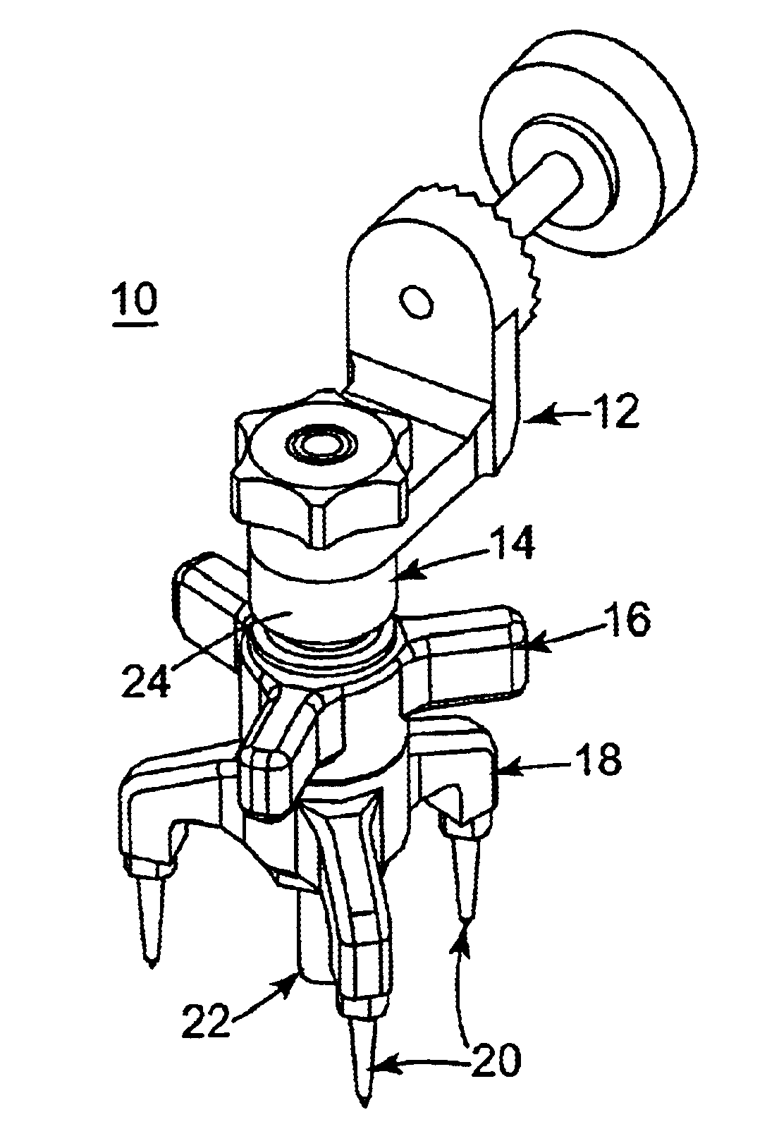
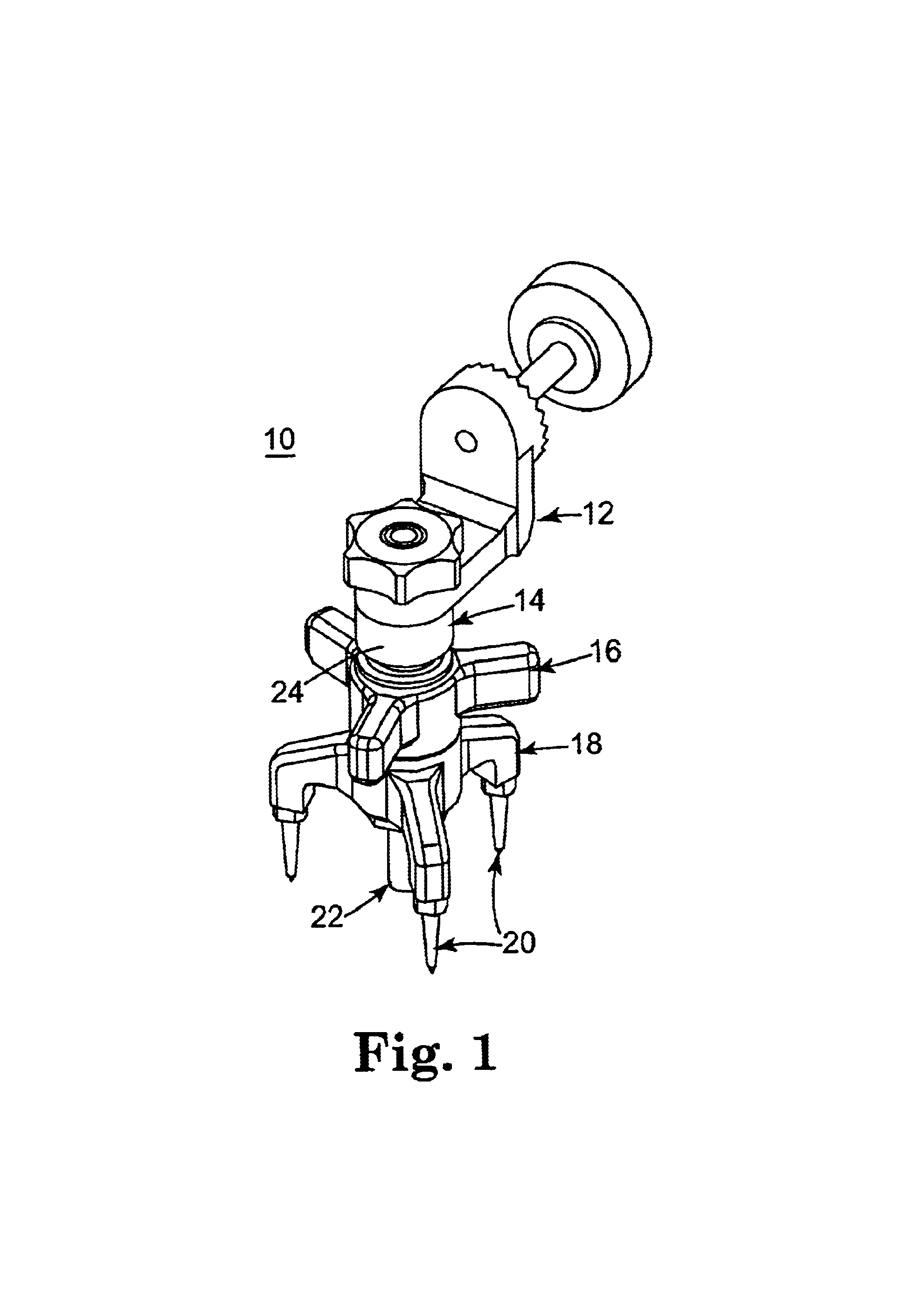
[0018]One preferred embodiment of a fixation device 10 in accordance with the present invention is provided in FIG. 1. Although not illustrated, it will be understood that the fixation device 10 is for use with a stereotactic image guidance system (not shown), an example of which is available under the trade name LandMarX® from Medtronic-Xomed, and in particular, for maintaining a reference frame (not shown), such as a dynamic reference frame. With this in mind, the device 10 includes a mounting bracket assembly 12, a cannulated post 14, a wing nut 16, a base 18, a plurality of percutaneous pins 20, and an anchor tube 22. Details on the various components are provided below. In general terms, however, the cannulated post 14 is selectively coupled to the mounting bracket assembly 12. The cannulated post 14 includes a central portion 24 at which the wing nut 16, and below which the base 18 and the anchor tube 22, are secured. More particularly, the anchor tube 22 extends distally from a


PUM


Abstract

A surgical fixation device for mounting a stereotactic reference frame to a patient. The device includes a mounting bracket assembly, a cannulated post, a base, an anchor tube, a plurality of percutaneous pins, and a driving device. The mounting bracket assembly is connected to a top portion of the post, whereas the base is slidably coupled to a bottom portion of the post, and defines a plurality of legs. The anchor tube extends distally from the post. The percutaneous pins extend distally from the legs, respectively. Finally, the driving device is connected to the post and is adapted to selectively contact the base. Upon final assembly, the base is longitudinally moveable relative to the anchor tube. The base can be moved to a retracted position such that the anchor tube is readily securable to a bony structure of the patient's anatomy. Once secured, the base can be moved distally such that the percutaneous pins engage the bony structure as well, thereby promoting overall stability of the device.

Description


Claims


Application Information

Patent Timeline
Owner MEDTRONIC INC
Why Eureka
Try Eureka