Wide-band tapered-slot antenna for RF testing

Inactive Publication Date: 2005-05-31
AVAGO TECH WIRELESS IP SINGAPORE PTE
View PDF8 Cites 12 Cited by
  • Summary
  • Abstract
  • Description
  • Claims
  • Application Information

AI Technical Summary

Benefits of technology

[0008]Accordingly, the present invention provides methods and apparatus for testing wireless devices. A new asymmetric wide-band tapered-slot antenna with a new feed port has been developed. In one embodiment of the present invention, this tapered-slot antenna is used in a test box for testing phones. Using this antenna, test measurement variations are reduced. In particular, in a specific embodiment the variation in insertion loss among test boxes is reduced by a factor of ten.

Problems solved by technology

A bad unit may be nonfunctioning, or may not perform as well as its designers intend.
Each bad unit shipped costs the manufacturer in terms of customer satisfaction, brand loyalty, and goodwill.
Each good unit not shipped may mean that it is retested or replaced, or that a sale is lost.
Unfortunately, in a manufacturing environment, there are variations in readings from one box, as well as among boxes.
These variations reduce yield and lower quality control.
Also, the back plug cable connectors tend to wear out, and require replacing.
The time needed to install and adjust the new boxes adds to a phone's cost.

Method used


Image

  • Wide-band tapered-slot antenna for RF testing
  • Wide-band tapered-slot antenna for RF testing
  • Wide-band tapered-slot antenna for RF testing

Examples


Example

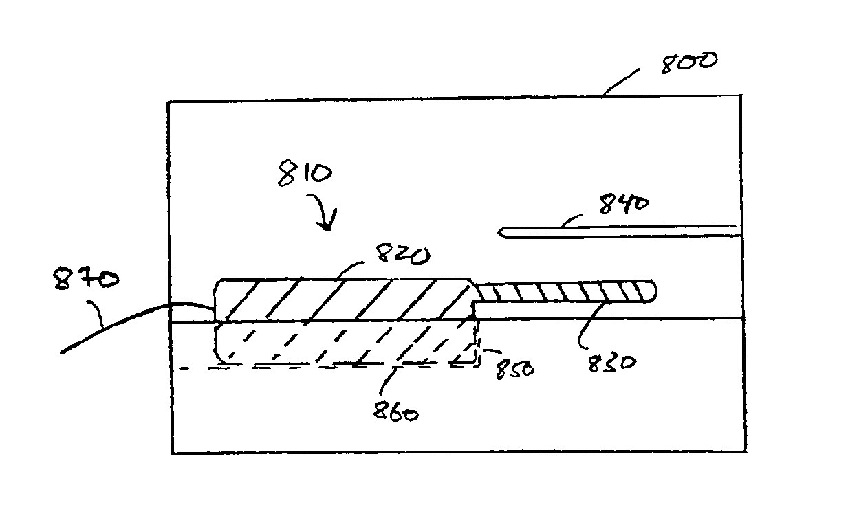
[0030]FIG. 1 illustrates a wireless phone 110 in a conventional test box 100. This figure, as with all the included figures, is shown for illustrative purposes only, and does not limit either the possible applications of embodiments of the present invention, or the claims.

[0031]The wireless phone 110 has a body 120 and antenna 130. The phone rests on support surface 160 against stop 150, such that antenna 130 is approximately aligned to test antenna 140. The phone is connected to a test system (not shown) by system connector 170. The system connector 170 typically plugs into the bottom of the phone. A back plug cable 180 may also connect the phone to the test system. The back plug is an RF connector on the phone's PCB, usually near the antenna, and the back plug cable 180 connects to the phone at the back plug.

[0032]If the back plug is used, testing is simplified since there is no need to align the phone antenna 130 to a test antenna 140—test signals are sent and received using the bac


PUM


Abstract

Methods and apparatus for testing wireless devices. Devices being tested receive and transmit radio frequency test signals. These radio frequency test signals are received or transmitted using an antenna associated with the device, and then are transmitted or received using a unique wide-band tapered-slot antenna connected to a test system. The wide-band tapered-slot antenna has an input path that is substantially orthogonal to the tapered slot, and one of the conductors defining the slot is grounded.

Description


Claims


Application Information

Patent Timeline
Owner AVAGO TECH WIRELESS IP SINGAPORE PTE
Why Eureka
Try Eureka