Actuating pedal for the brake system of road vehicles

a technology for actuating pedals and brake systems, which is applied in the direction of mechanical control devices, instruments, manual control with single controlling members, etc., can solve the problems of high production cost of actuating pedals of this class, high production cost, and relatively heavy weight, and achieve optimal actuation feeling, simple shape, and greater pedal angle

Inactive Publication Date: 2005-09-20
ZF LEMFOERDER METALLWAREN AG
View PDF18 Cites 3 Cited by
  • Summary
  • Abstract
  • Description
  • Claims
  • Application Information

AI Technical Summary

Benefits of technology

This patented technology allows for integration into different parts of the car's interior dashboard while maintaining their strength and durability. It includes adding extra components like springs and cushions to improve shock absorption performance when activate certain functions inside the dash board. Additionally, there is a way to attach these added devices onto the outside of the dashboards through injectmable methods instead requiring expensive materials. Overall, this innovative solution improves safety standards and reduces costs associated with producing cars due to increased efficiency and functionality provided by integrations between them.

Problems solved by technology

This patented describes how powerful force can cause damage when driving certain parts of a car's steering wheel by applying too much pressure over its connections due to sudden stops caused by external factors like potholes or rocks under road conditions. To prevent such issues, some existing solutions involve adding extra reinforcement elements around specific areas where there could occur more severe impact than others. However, current methods require costly machining operations before painting, making them heavier but less effective against accidents involving large amounts of material usage.

Method used


Image

  • Actuating pedal for the brake system of road vehicles
  • Actuating pedal for the brake system of road vehicles
  • Actuating pedal for the brake system of road vehicles

Examples


Embodiment Construction

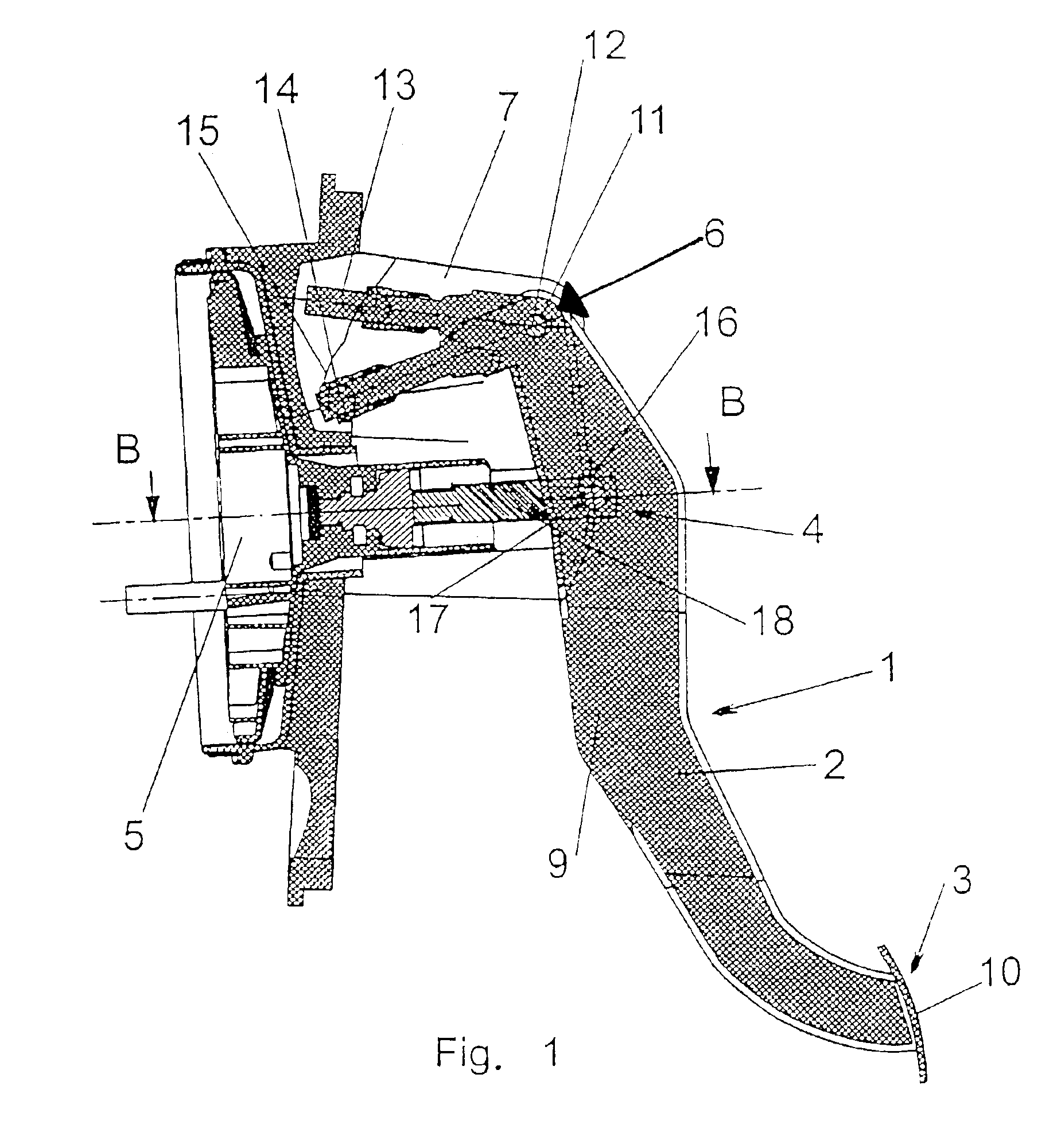
[0017]Referring to the drawings in particular, the actuating pedal for the brake system of a road vehicle, which is designated by 1 in its entirety in FIG. 1, has essentially a pedal body 2, an actuating surface 3, a connection device 4 to a brake power booster module 5, and a fastening device 6 for fixing the actuating pedal 1 on a pedal block 7 of the road vehicle, which said pedal block is a rigid part of the body.

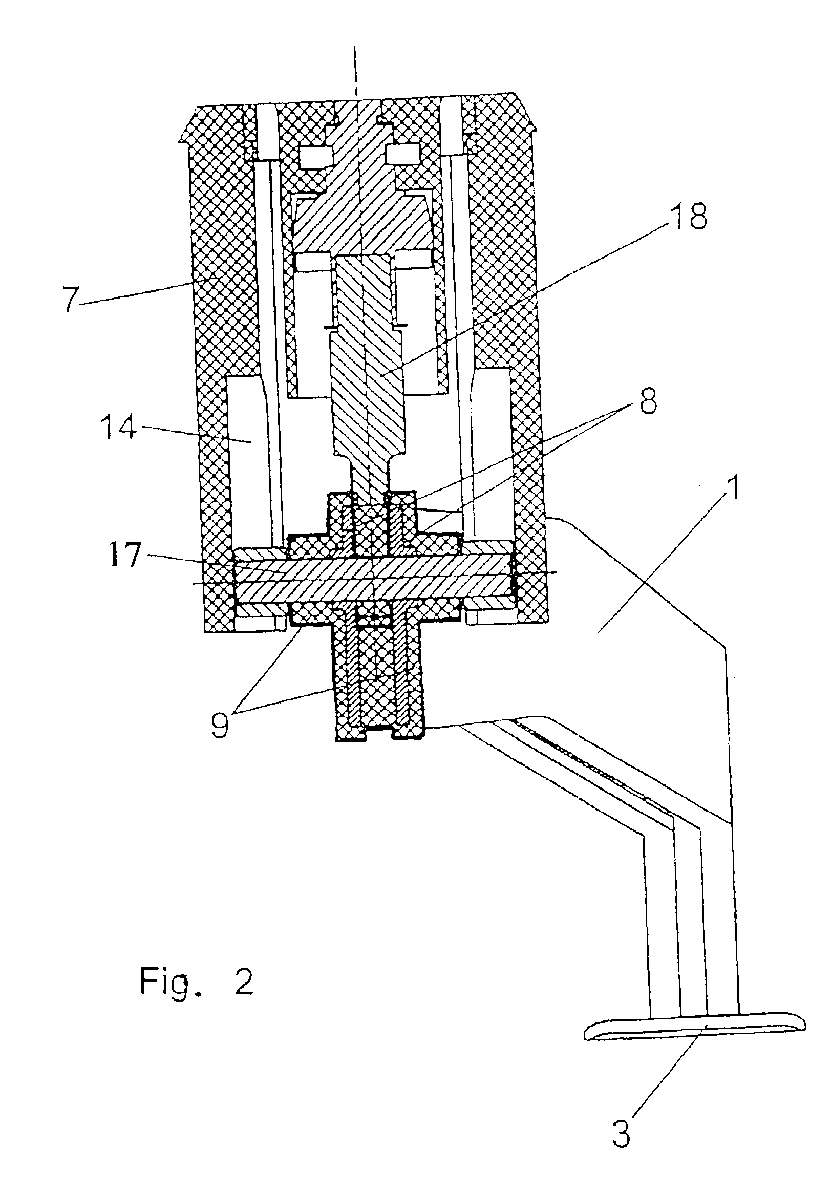
[0018]The pedal body 2 comprises two inner metal cores 8, which are completely surrounded by a plastic jacketing 9 consisting of PA 6 or PA 6.6 / GF, as is apparent from FIG. 2. The metal cores 8 have essentially a rectangular cross section in this exemplary embodiment, which is particularly advantageous with respect to the required torsional rigidity of the actuating pedal. In the area of the connection device 4, the metal cores are provided with a recess each, through which a pin element 13 of the connection device is passed through. This design of the metal cores 8 with


PUM


Abstract

An actuating pedal (1) for the brake system of a road vehicle has a fastening device (6) for fixing the actuating pedal (1) in a pivot bearing (12) on a pedal block (7) of the vehicle. The pedal block is a rigid part of the body, with a pedal body (2) and with an actuating surface (3). The pedal body (2) has at least one inner metal core (8) and a plastic jacketing (9) surrounding the metal core (8).

Description


Claims


Application Information

Patent Timeline
Owner ZF LEMFOERDER METALLWAREN AG
Why Eureka
Try Eureka