Polarization plate

Inactive Publication Date: 2005-11-29
NORTH SOUTH HLDG
View PDF14 Cites 7 Cited by
  • Summary
  • Abstract
  • Description
  • Claims
  • Application Information

AI Technical Summary

Problems solved by technology

However, it should be appreciated that the use of polarization introduces additional complexity into the circuitry of the communication infrastructure.
Accordingly, the use of orthogonal polarization can require multiple variations in the equipment utilized, causing inefficiencies in the manufacture and supplying of such equipment as multiple versions of the equ

Method used


Image

  • Polarization plate
  • Polarization plate
  • Polarization plate

Examples


Embodiment Construction

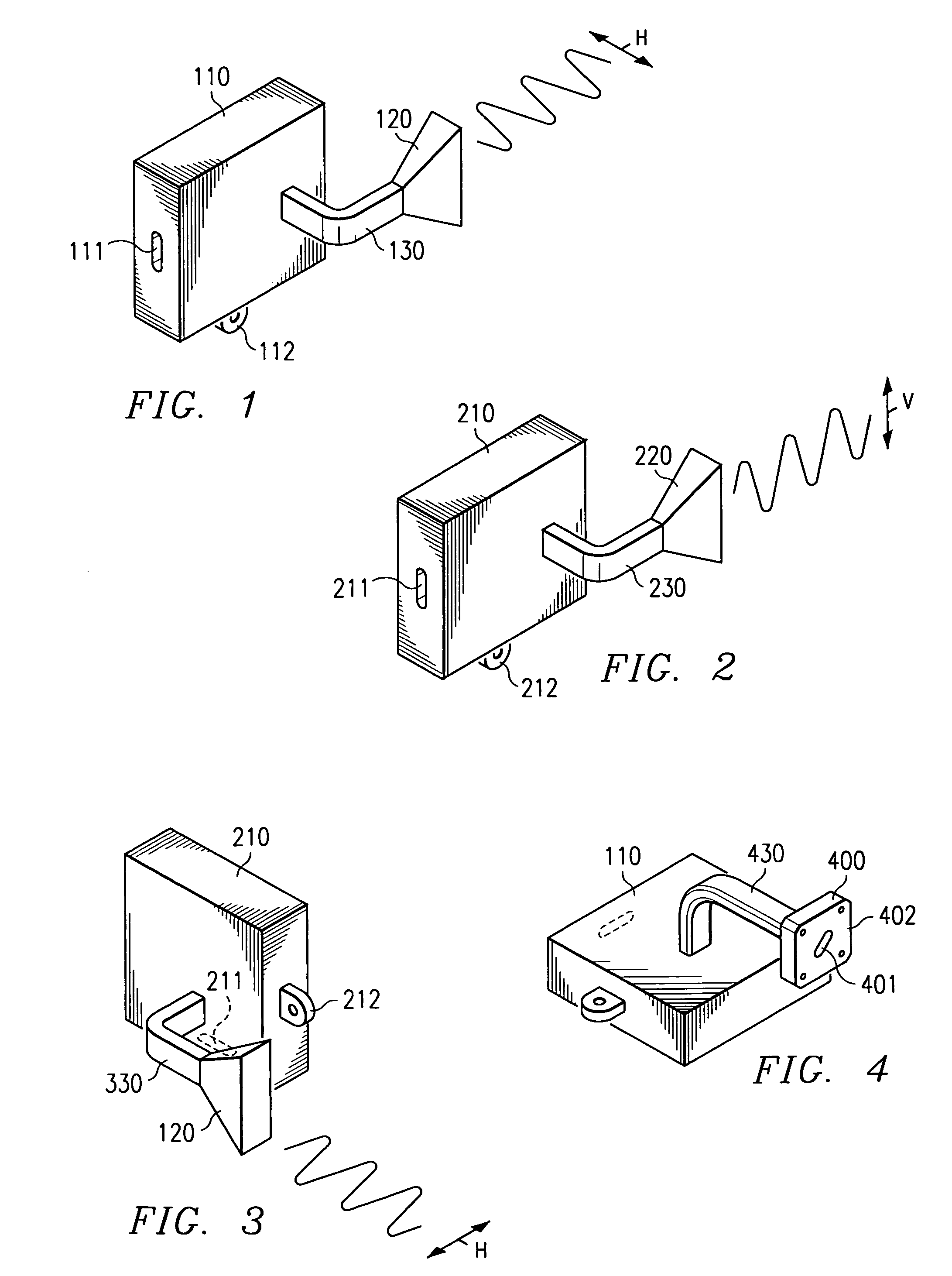
[0024]Directing attention to FIG. 1, a transceiver and antenna assembly such as may be utilized to provide information communication via an air, gap as radio frequencies in the range of 2 to 110 GHz is shown. Here transceiver unit 110 is coupled to antenna 120 via waveguide 130. Transceiver unit 110 may provide only a portion of the circuitry necessary to utilize the communicated information, such as the duplexing circuitry, filters, and up / down converters of the front end circuitry disclosed in the above referenced patent application entitled “Millimeter Wave Front End.” Accordingly, transceiver unit 110 may include an electrical interface, such as connector 111, adapted to couple additional electronic circuitry to the transceiver unit. Additionally, transceiver unit 110 may include hardware, such as connector 112 disposed for the mounting of the transceiver unit and / or the coupled antenna.

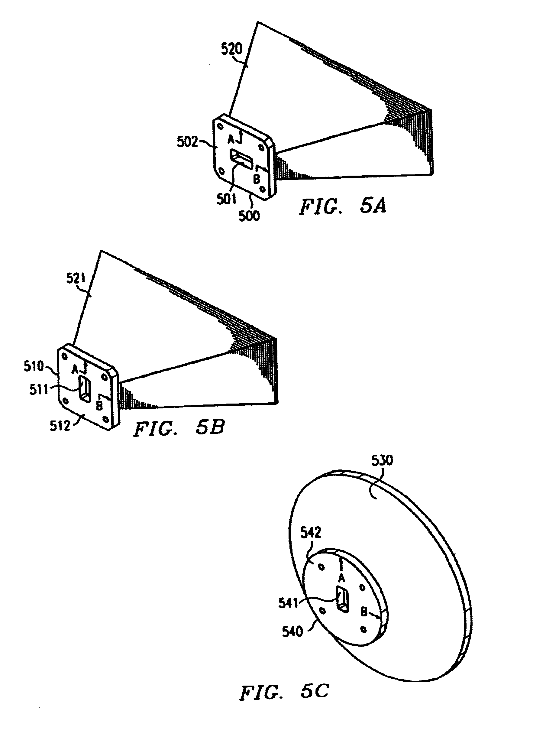
[0025]It shall be appreciated that antenna 120 of FIG. 1 is adapted to provide communication


PUM


Abstract

The present invention discloses a system and method by which radio transceiver equipment may be coupled to antenna equipment polarized in either of two orthogonal polarizations without requiring any adaptation or additional componentry while providing the same signal path attributes irrespective of the polarization chosen. Accordingly, a single transceiver/antenna unit may be utilized for providing communications polarized vertically, or slant right, and polarized horizontally, or slant left.

Description


Claims


Application Information

Patent Timeline
Owner NORTH SOUTH HLDG
Why Eureka
Try Eureka