Method for calibration of a vectorial network analyzer having more than two ports

a network analyzer and network analyzer technology, applied in the direction of instruments, resistance/reactance/impedence, measurement devices, etc., to achieve the effect of improving measurement accuracy

Inactive Publication Date: 2010-08-03
CASCADE MICROTECH
View PDF2 Cites 2 Cited by
  • Summary
  • Abstract
  • Description
  • Claims
  • Application Information

AI Technical Summary

Benefits of technology

The technical effect of this patented technology is that it provides a way to make sure that network analyzers have accurate measurements without requiring users' knowledge or permission from others. This can be done through transmitting standardized data over multiple different types of networks, such as communication lines or optical fibers.

Problems solved by technology

The technical problem addressed in this patent text is how to accurately define and correct nonlinearities in multiple measurement points in a wireless communication system without requiring complicated calculations.

Method used


Image

  • Method for calibration of a vectorial network analyzer having more than two ports
  • Method for calibration of a vectorial network analyzer having more than two ports
  • Method for calibration of a vectorial network analyzer having more than two ports

Examples


Embodiment Construction

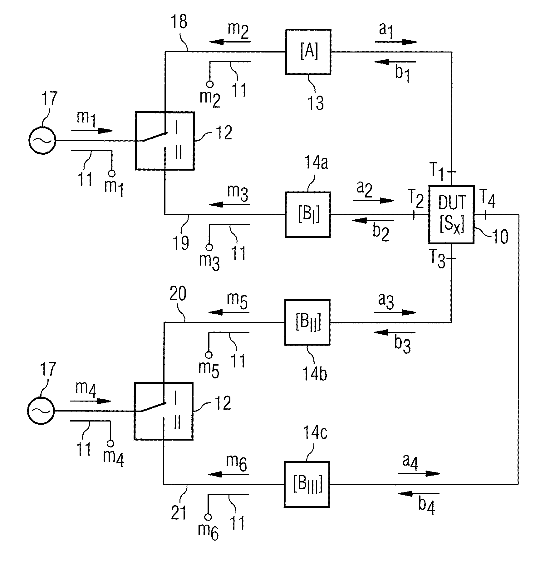
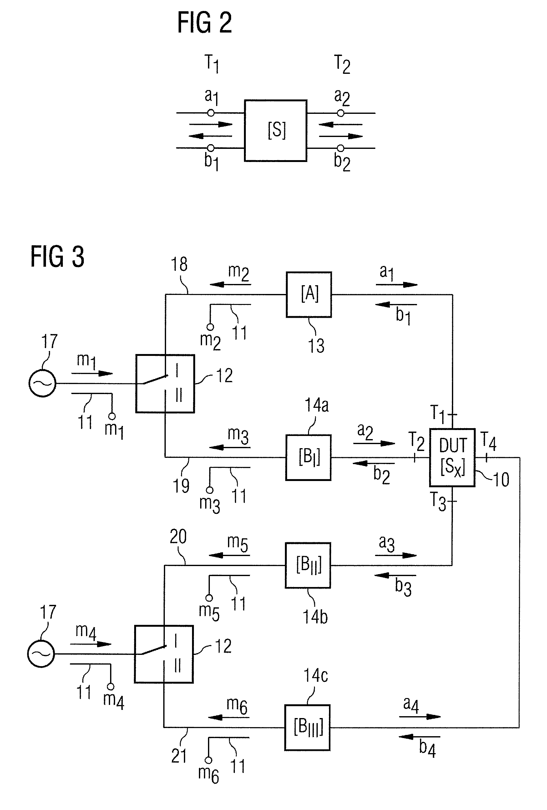
[0046]FIG. 3 illustrates how the signal from one of two sources 17 is conducted via a first changeover switch 12 onto the branches 18 and 19; and the signal from a second source 17 is conducted via a second changeover switch 12 onto the branches 20 and 21. Both changeover switches 12 are arranged in front of the measurement sites 11 for the waves reflected into the respective branches 18, 19, 20, and 21 (referred to here as m2 and m3 as well as m5 and m6). Two additional measurement sites 11 (referred to as m1 and m4), which make a measure of the incident waves, are arranged between a respective source 17 and a switch.

[0047]Thus, the measurement sites 11, assumed to be ideal, are viewed in the propagation direction of the wave to be measured, are always arranged in front of a switch 12, and in each case make a measurement of the incident and transmitted wave. The properties of the switches 12—such as repeatability, reflection and long-term stability—are taken into account in the follow


PUM


Abstract

Method for calibrating a vectorial network analyzer, with n measurement ports (n>2) and at least m measurement sites, where m>n+1 includes measurement of three different n-port reflection standards, connected between measurement ports in any desired order, and successive measurement of reflection and transmission parameters at different transmission standards, connected between two respective measurement ports, and computational determination of error coefficients and error-corrected scattering matrices [Sx] of the n-port standards. Reflection standards, Short and Open, are unknown, but physically identical at each n-fold one-port. Reflection standard, realized by wave terminations, is known, but can be different at each n-fold one-port. Transmission standards are measured at a transmission standard, having known length and attenuation at a two-port, and at unknown transmission standards, identical for incident and reflected waves at remaining two-ports, which can be connected. Unknown reflection and transmission values are determined computationally by the measurements.

Description


Claims


Application Information

Patent Timeline
Owner CASCADE MICROTECH
Why Eureka
Try Eureka