LED driver with inherent current limiting and soft startup capability

Inactive Publication Date: 2016-01-12
UNIVERSAL LIGHTING TECHNOLOGIES
View PDF3 Cites 1 Cited by
  • Summary
  • Abstract
  • Description
  • Claims
  • Application Information

AI Technical Summary

Benefits of technology

[0009]A low-cost, dimmable and inductor-less LED driver as disclosed herei

Problems solved by technology

However, additional problems arise from their use.
For example, most AC mains-driven LED drivers have complicated current control requirements, and cannot effectively solve turn-on “in

Method used


Image

  • LED driver with inherent current limiting and soft startup capability
  • LED driver with inherent current limiting and soft startup capability
  • LED driver with inherent current limiting and soft startup capability

Examples


Embodiment Construction

[0023]Referring generally to FIGS. 1-3, various exemplary embodiments of the invention may now be described in detail. Where the various figures may describe embodiments sharing various common elements and features with other embodiments, similar elements and features are given the same reference numerals and redundant description thereof may be omitted below.

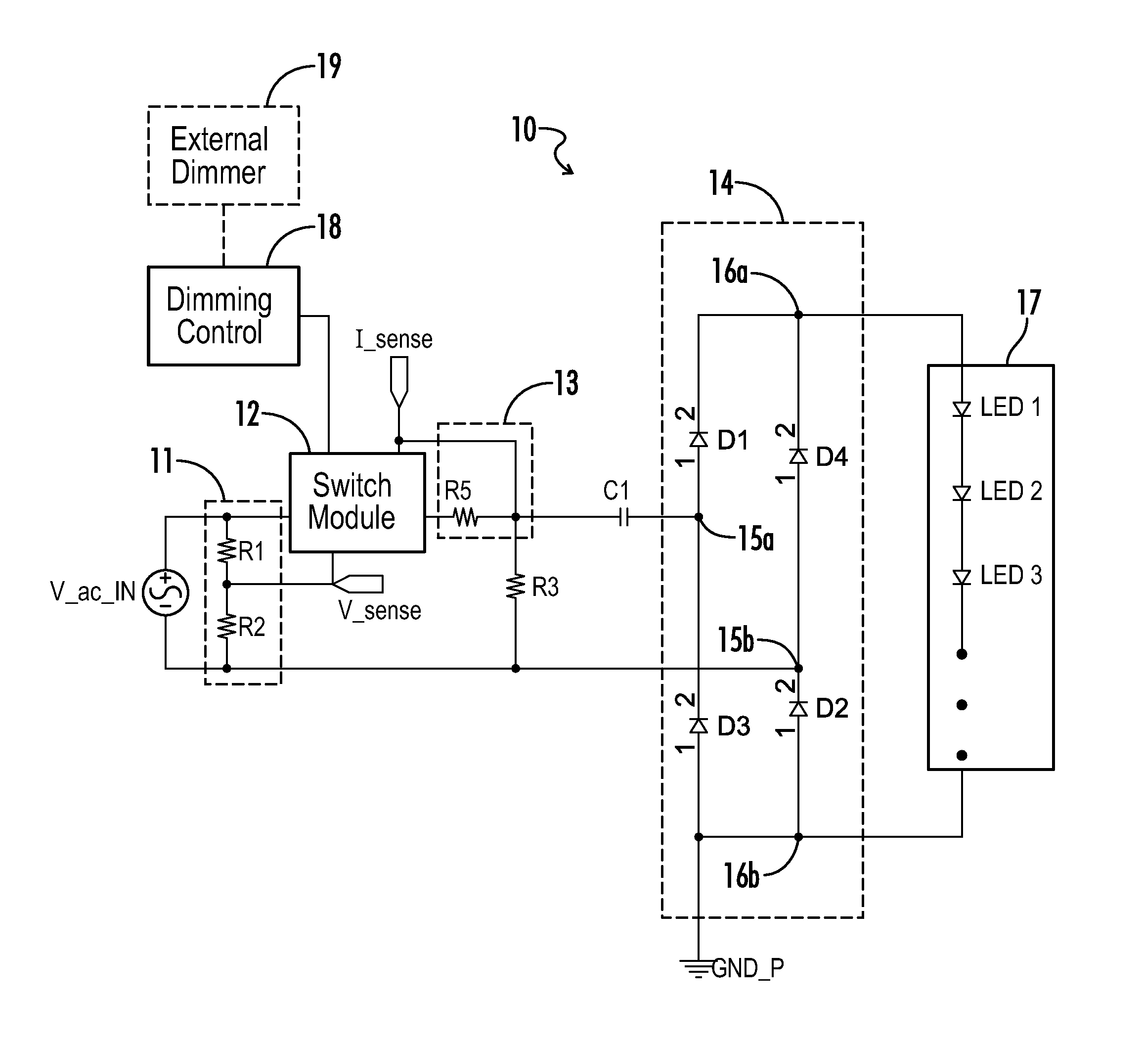
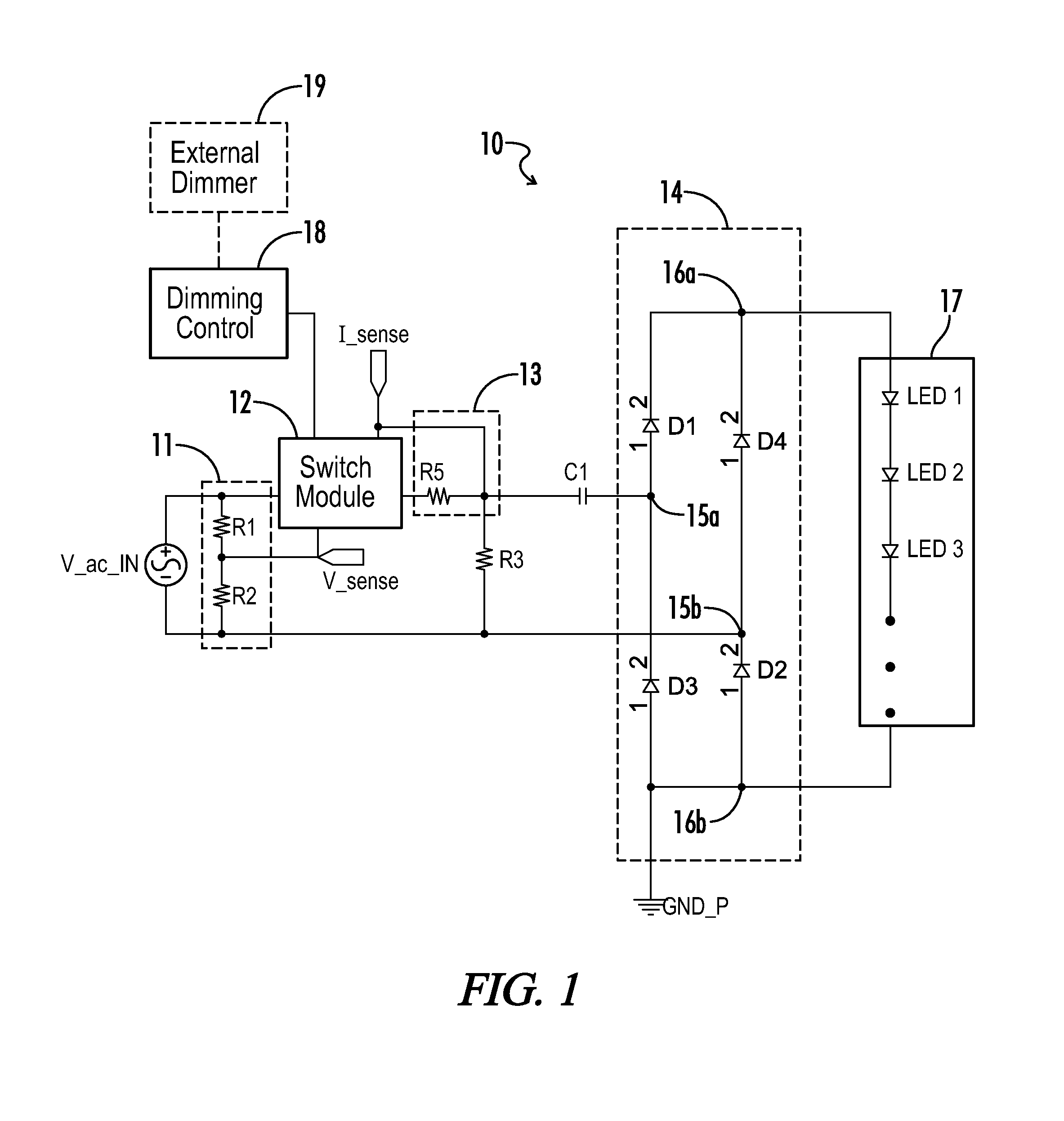
[0024]As represented in FIG. 1, an exemplary LED driver 10 includes an input end which may be connected to an input AC voltage source V_ac_IN. A voltage sensor 11 is coupled across the input terminals and may be formed by a voltage divider including resistors R1 and R2. In the example shown, a node between the resistors R1, R2, is coupled to feed back the sensed voltage (V_sense) to a controllable switch module 12. A current sensing resistor R5 is coupled to an output end of the switch module 12, with an output from the resistor being coupled back to the switch module 12 for current sensing feedback (I_sense). A current limiting c


PUM


Abstract

An inductor-less LED driver circuit is provided with soft startup and inherent current limiting capabilities. A diode rectifier is coupled across an AC mains input, with the outputs for the rectifier coupled directly across an LED array. A bi-directional switching circuit and current limiting capacitor are coupled in series between a first mains input and a first rectifier input. A controller turns the bi-directional switching circuit on and off to enable or disable conduction of power from the AC power source, wherein the bi-directional switching circuit is turned on in association with a detected zero voltage state for AC input power, and the bi-directional switching circuit is turned off in association with a detected zero current state for AC input power. The controller further adjusts switch states for the bi-directional switching circuit in response to a dimming control signal corresponding to a desired lighting output level.

Description


Claims


Application Information

Patent Timeline
Owner UNIVERSAL LIGHTING TECHNOLOGIES
Why Eureka
Try Eureka