Structure of turbine blade wheel weight reducing for pressurizer

A turbocharger turbine and new structure technology, applied in the direction of machines/engines, engine components, internal combustion piston engines, etc., can solve the problems of uneven mass distribution of supercharger rotors, insufficient linear speed, insufficient welding strength, etc., and achieve mass production The production economic benefit is obvious, the effect of reducing weight and saving materials

Inactive Publication Date: 2007-07-18
BEIJING INSTITUTE OF TECHNOLOGYGY
View PDF0 Cites 6 Cited by
  • Summary
  • Abstract
  • Description
  • Claims
  • Application Information

AI Technical Summary

Problems solved by technology

[0003] For automotive turbochargers, in the friction welding process of the turbine impeller and shaft, due to the small radius, the linear velocity during friction welding is insufficient, resulting in insufficient welding st

Method used


Image

  • Structure of turbine blade wheel weight reducing for pressurizer

Examples


Embodiment Construction

[0017] The specific embodiment of the present invention is given in detail by the following examples.

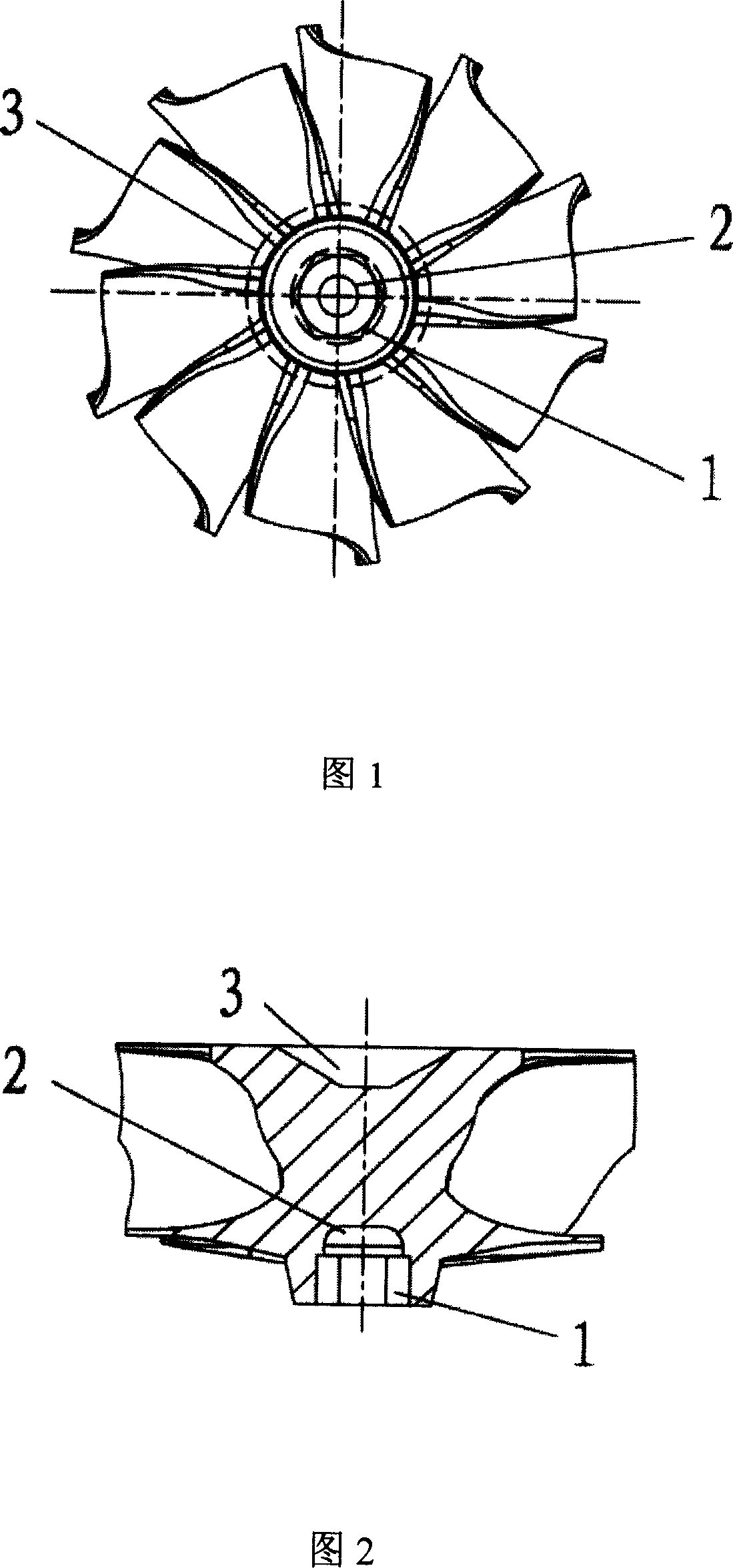
[0018] The supercharger turbine impeller lightening type structure is characterized in that: the inner hexagon (1) is concentric with the turbine impeller and is located outside the weight reducing hole (2) for the positioning and assembly of the supercharger rotor; the weight reducing hole (2) Concentric with the turbine impeller, located inside the inner hexagon (1) and communicated with it; the friction welding taper hole (3) is located on the back side of the wheel, concentric with the turbine impeller, used for friction welding with the shaft, and can increase the effectiveness of friction welding welding area.

[0019] Product manufacturing implementation mode: The product of the present invention is to effectively reduce the weight of the turbocharger parts and components on the basis of not changing the blade shape and flow channel and ensuring the performance and struc


PUM


Abstract

The present invention belongs to the field of engine part technology in mechanical engineering, and is especially weight reducing new structure of turbo impeller for vehicular turbocharger. The weight reducing new structure of turbo impeller includes internal hexagonal hole concentric with turbo impeller and outside the lightening hole for the location and assembling of the rotor of the supercharger, lightening hole concentric with turbo impeller and communicated to the internal hexagonal hole, and conic hole concentric with turbo impeller for the friction welding of the shaft. The weight reducing new structure is determined through numerical analysis, structure optimization, etc. The present invention has the advantages of effectively reduced turbo impeller weight, saving in material, reduced cost, raised connection strength between turbo impeller and shaft, etc.

Description


Claims


Application Information

Patent Timeline
Owner BEIJING INSTITUTE OF TECHNOLOGYGY
Why Eureka
Try Eureka