Embedded type software debugging device, and method for implementing debugging

A technology of embedded software and implementation method, which is applied in the direction of software testing/debugging, etc., and can solve problems such as occupation and affecting CPU performance

Inactive Publication Date: 2007-07-25
ZHEJIANG UNIV
View PDF0 Cites 18 Cited by
  • Summary
  • Abstract
  • Description
  • Claims
  • Application Information

AI Technical Summary

Benefits of technology

The technical effect that this technology helps users see what they have done for their programs while still being able to run them smoothly over time by sending all necessary data from main storage locations instead of relying on specific hardware components like CPUs or memristors. This makes it easier than previous methods because there was no resource left behind even if some parts were idle waiting for new tasks to be performed again later.

Problems solved by technology

This patents describes different ways to improve the efficiency at developing embedded systems without requiring significant effort or expensive equipment. One way involves adding extra components into the original system before compiling them onto another piece of hard disk called the stab module. By doing this process, any bugs found during testing may have been corrected while they were discovered later. Another option includes embedding specific function blocks within the main chip's firmware instead of directly modifying its own functionality. These techniques aim to simplify the debugging task and ensure accurate results from low resource environments like embedded devices.

Method used


Image

  • Embedded type software debugging device, and method for implementing debugging
  • Embedded type software debugging device, and method for implementing debugging
  • Embedded type software debugging device, and method for implementing debugging

Examples


Embodiment Construction

[0035] With reference to accompanying drawing, the present invention will be described in detail below:

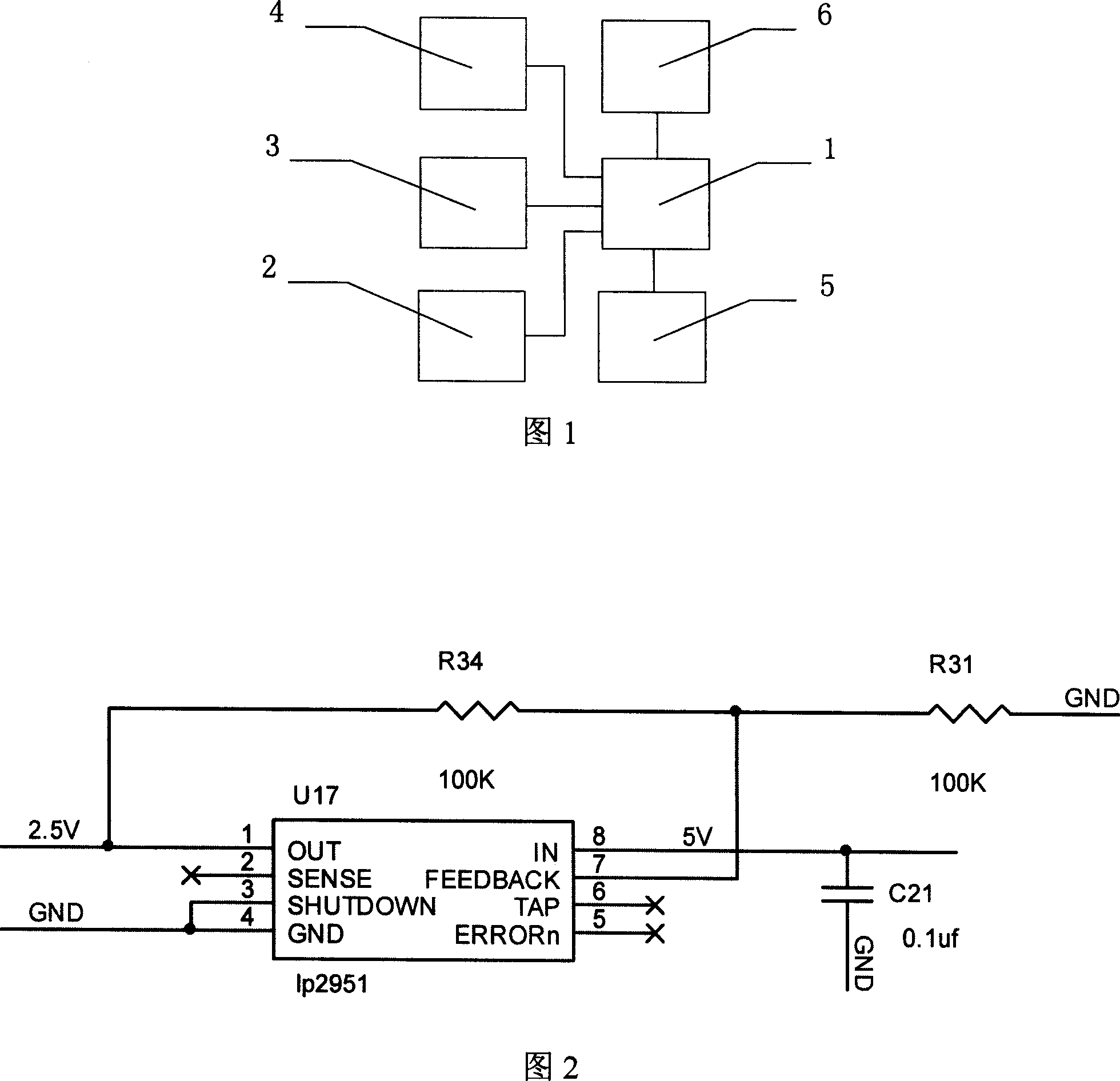
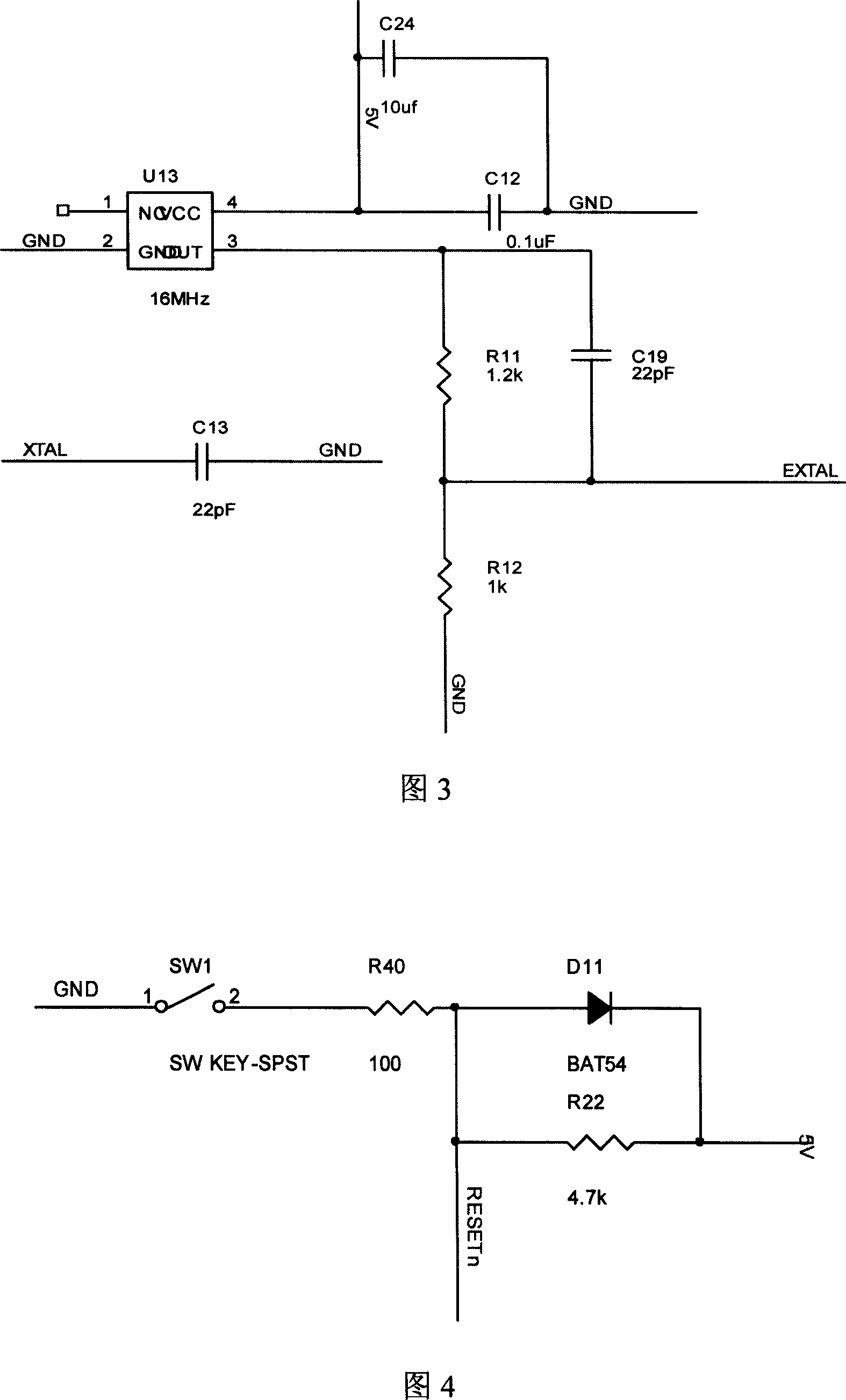
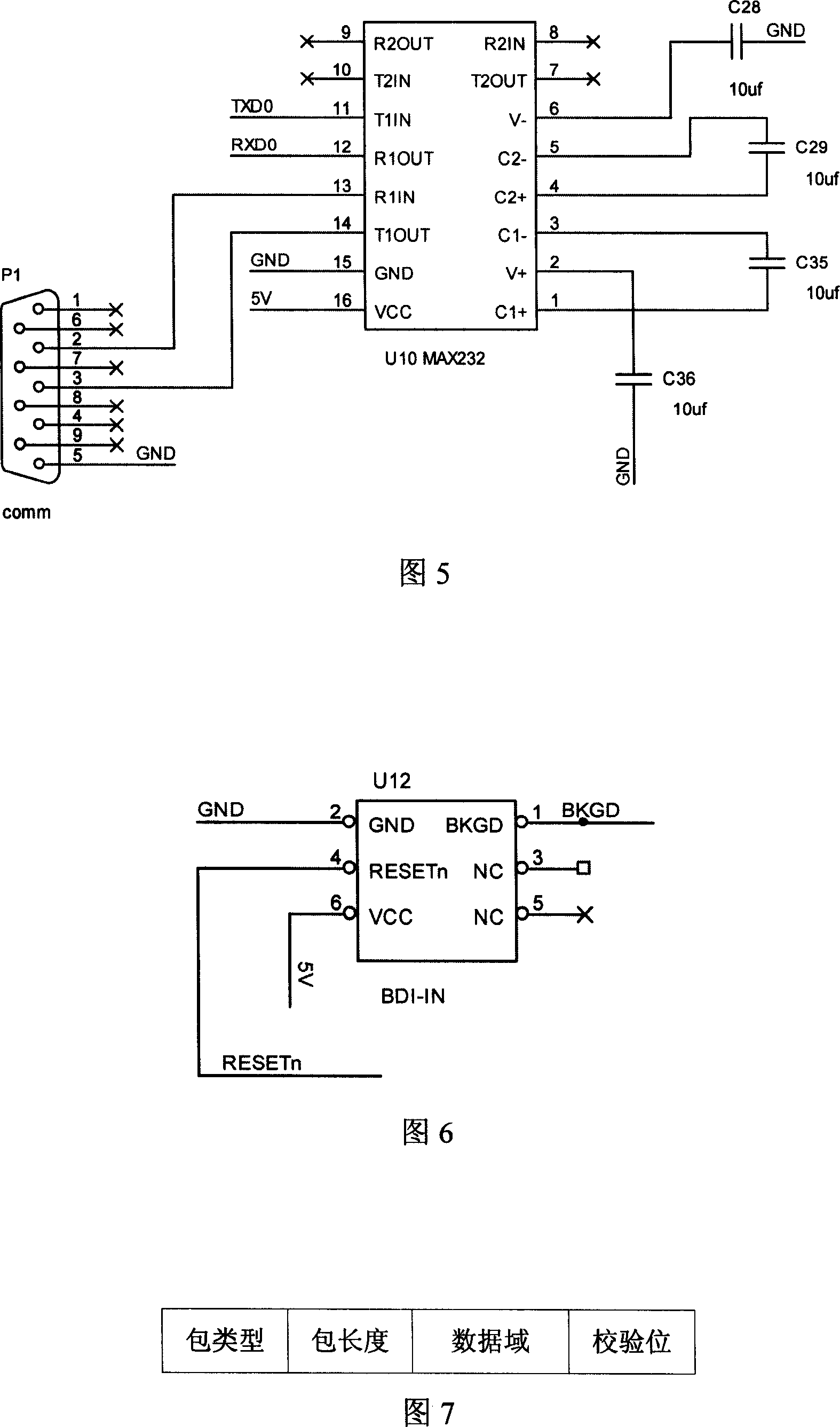
[0036] The present invention is further introduced below, and the present embodiment adopts Motorola HCS12 chip 1 as main control chip, and its peripheral circuit includes power supply circuit 2, clock circuit 4, reset circuit 3, serial port level conversion circuit 6 and debugging interface circuit 5, The power supply circuit 2, clock circuit 4, reset circuit 3, serial port level conversion circuit 6 and debugging interface circuit 5 are all connected to the main control chip. The functions of each circuit are introduced as follows:

[0037] (1) Power circuit:

[0038] The Motorola HCS12 chip requires both 5V and 2.5V power supplies. The 5V power supply is obtained from the target machine by the debugging interface circuit, as shown in Figure 6. The 2.5V power supply is obtained through further voltage regulation from the 5V power supply, and the LP2951 power supply chip


PUM


Abstract

A method for debugging software of embedded type includes realizing serial interface communication protocol, realizing analysis and package mechanism of packet and realizing communication protocol of background debugging mode based on Motorola HCS 12 chip. The device used for realizing said method is also disclosed.

Description


Claims


Application Information

Patent Timeline
Owner ZHEJIANG UNIV
Why Eureka
Try Eureka