Sliding, side hung and rotary three-purpose antitheft window

A three-in-one, anti-theft window technology, applied in the field of anti-theft windows, can solve the problems of poor sealing, inconvenient maintenance, poor safety, etc., and achieve the effects of reliable anti-theft function, convenient installation and maintenance, and convenient positioning and locking.

Inactive Publication Date: 2007-08-22
王金良
View PDF1 Cites 5 Cited by
  • Summary
  • Abstract
  • Description
  • Claims
  • Application Information

AI Technical Summary

Benefits of technology

This patented technology improves upon existing windows by connecting both end parts of each section together through pivotable connections between them that allow for even weight distribution when being pushed or pulled without biasing forces from other sections. Additionally, this design allows for easy mountability during construction due to its own self-weight system. Overall, these technical improvements improve safety performance and durability over older designs.

Problems solved by technology

This patents describes different types of doors or windows used in house constructions: slide door, cascade gate, and laminated glass (LFG). Each type has their own benefits and drawbacks compared to others like traditional shutters due to limitations such as weight and limited functionality. Additionally, these structures can become bulky during operation because they require more material than usual, making them hard to install and maintain over time.

Method used


Image

  • Sliding, side hung and rotary three-purpose antitheft window
  • Sliding, side hung and rotary three-purpose antitheft window
  • Sliding, side hung and rotary three-purpose antitheft window

Examples


Embodiment Construction

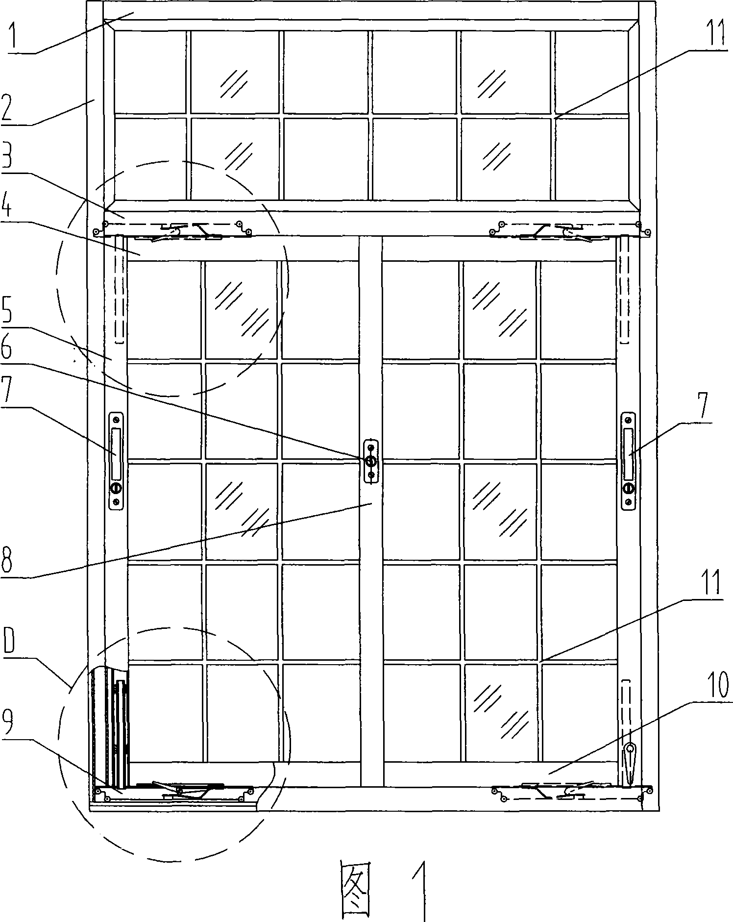
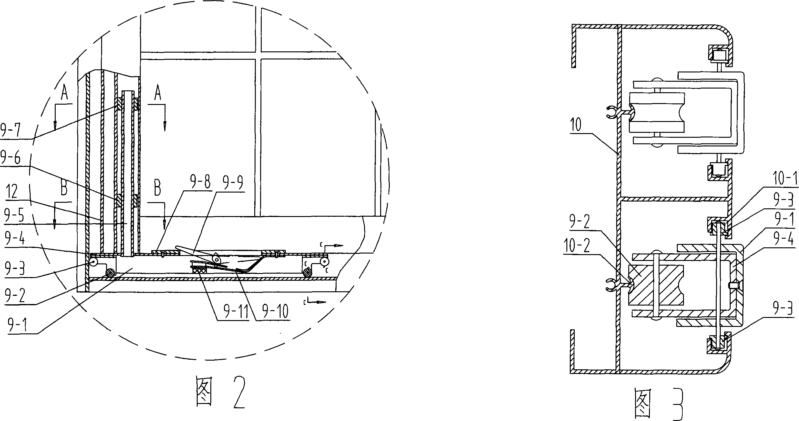
[0017] As shown in Fig. 1, Fig. 2 and Fig. 3, two roller brackets 9-4 are respectively installed at the two ends of the shaft bracket 9-1 of the shaft assembly 9, and two upper rollers 9 coaxially installed on the top of each group of roller brackets 9-4 -3 is embedded in the two rectangular guide grooves 10-1 of the upper and lower glideways 4 and 10, and the arc grooves on the lower rollers 9-2 at the bottom are close to the arc guide rails 10- in the upper and lower glideways 3 and 10 2 The upper, upper and lower rollers 9-3, 9-2 support the gravity and wind force of the window sash through the upper and lower slides 3, 10, without partial cutting, strong supporting force, safe and reliable, and can be extended to the left and right of the slides 3, 10 to achieve The push-pull function of the window sash.

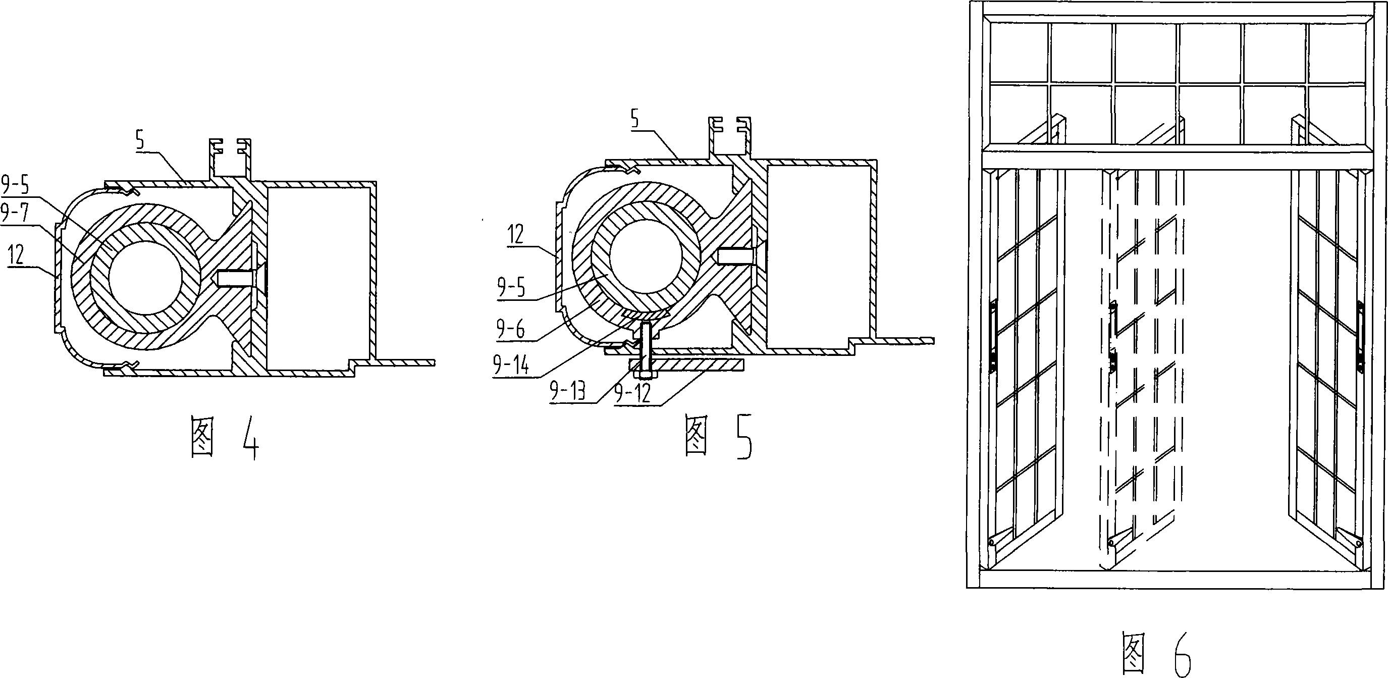
[0018] As shown in Fig. 1, Fig. 2, Fig. 4, and Fig. 5, the rotating shaft 9-5 vertically fixed on the upper end of the rotating shaft bracket 9-1 passes through the locking


PUM


Abstract

The present invention discloses a building component burglary-resisting window integrating the functions of side-hung window, sliding window and revolving window into one body. Its key component is the rotating shaft component formed from steel structure transversely arranged U-shaped rotating shaft supporting frame, upper and lower two groups of rollers and rotating shaft. Two groups of upper and lower rollers of two ends of said rotating shaft are set in the upper and lower slideways of window frame, said rotating shaft component can be leftwards and rightwards moved in the upper and lower slideways, and can be locked at any position so as to implement sliding opening or closing function of window sash. The rotating shaft vertically-fixed in the upper portion of the rotating shaft component is connected with bezel of window sash by utilizing positioning block and locking said positioning block, so as to implement horizontal opening and revolving functions of window sash.

Description


Claims


Application Information

Patent Timeline
Owner 王金良
Why Eureka
Try Eureka