Structure of the lamp chamber cover of vertical type dust collector

A vacuum cleaner and lamp house technology, applied in the field of upright vacuum cleaner lamp house cover structure, can solve problems such as difficult disassembly of the focus point, and achieve the effect of convenient operation procedures

Inactive Publication Date: 2007-10-31
LG ELECTRONICS (TIANJIN) APPLIANCES CO LTD
View PDF0 Cites 0 Cited by
  • Summary
  • Abstract
  • Description
  • Claims
  • Application Information

AI Technical Summary

Problems solved by technology

[0008] The lamphouse cover structure of the conventional vertical vacuum cleaner, the lamphouse cover is fo

Method used


Image

  • Structure of the lamp chamber cover of vertical type dust collector
  • Structure of the lamp chamber cover of vertical type dust collector
  • Structure of the lamp chamber cover of vertical type dust collector

Examples


Embodiment Construction

[0023] In order to further understand the invention content, characteristics and effects of the present invention, the following examples are given, and detailed descriptions are as follows in conjunction with the accompanying drawings:

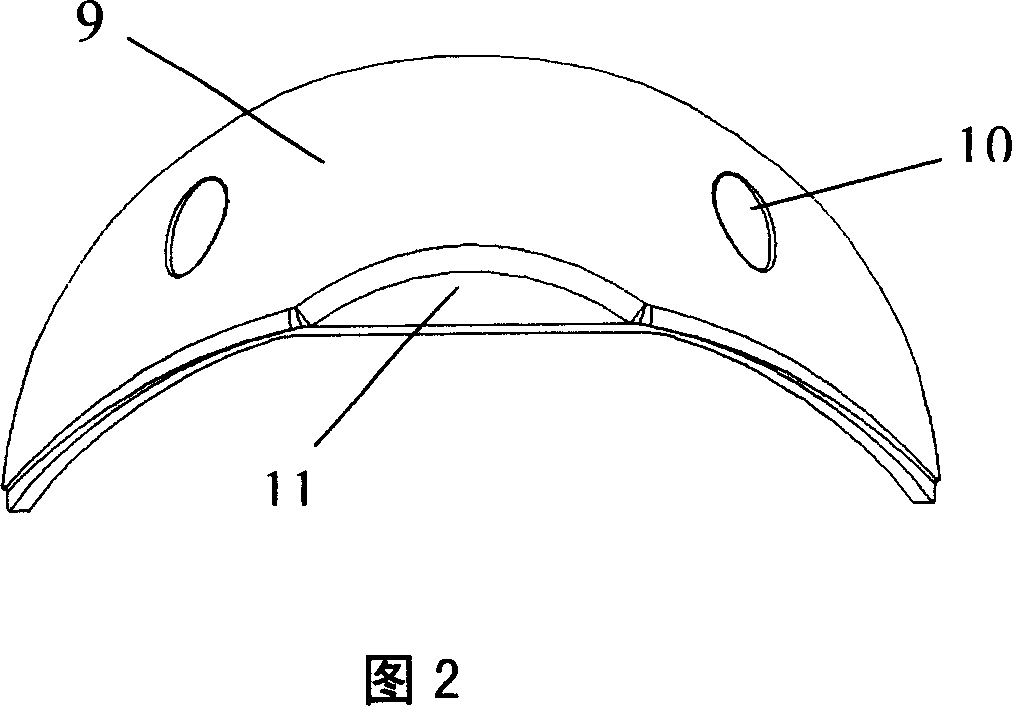
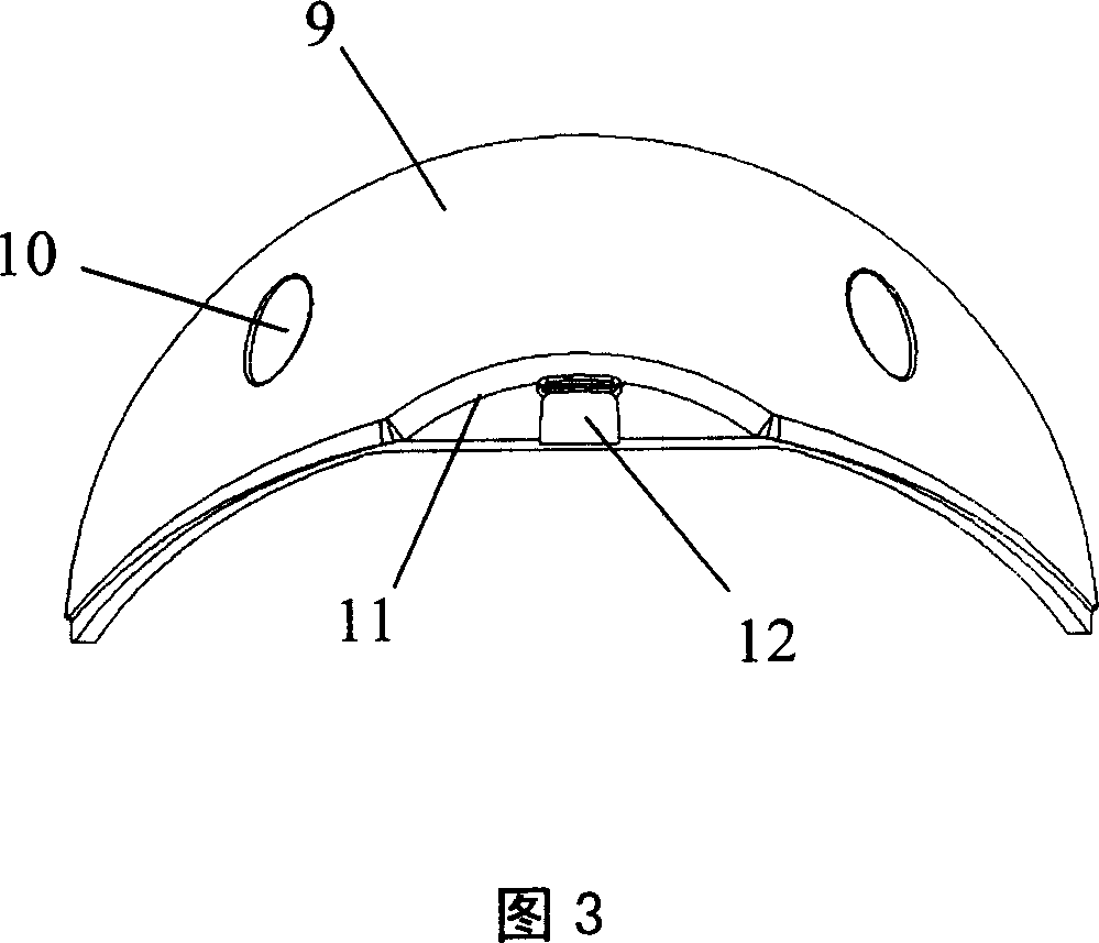
[0024] Fig. 2 is a schematic diagram of the structure of the lamphouse cover of the conventional upright vacuum cleaner, and Fig. 3 is a schematic diagram of the structure of the lamphouse cover of the upright vacuum cleaner of the present invention.

[0025] In the present invention, the same symbols are used for components that are the same as those in the prior art.

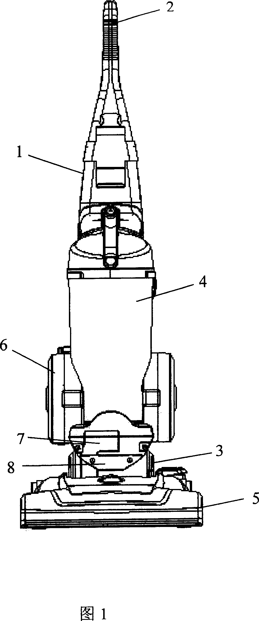
[0026] The upright vacuum cleaner includes a body 1. The upper part of the body 1 is a handle 2 that is convenient for users to push and pull. ) is plugged with a spare rigid vacuum tube (not shown), the bottom of the body 1 is provided with a suction nozzle 5 along the ground, and a rotatable roller brush (not shown) is arranged in the suction nozzle 5, and is fixed on the suct


PUM


Abstract

The invention discloses an aspirator structure with hand to support, which is characterized by the following: forming cover body with spherical arc half-angle; forming fixed hole at screwed hole in the lower of motor cover; forming arc dent in the middle of the lower edge in the cover body; forming a boss at the edge of the dent in the cover body. This invention can detach the lamp cover conveniently, which is convenient to operate.

Description


Claims


Application Information

Patent Timeline
Owner LG ELECTRONICS (TIANJIN) APPLIANCES CO LTD
Why Eureka
Try Eureka