Disk device
A chassis and disc-shaped technology, applied in recording information storage, instruments, etc., can solve the problems of disc looseness and alignment accuracy, drop, etc., and achieve the effect of eliminating looseness and high alignment accuracy.
- Summary
- Abstract
- Description
- Claims
- Application Information
AI Technical Summary
Problems solved by technology
Method used
Image

Examples
no. 1 Embodiment approach
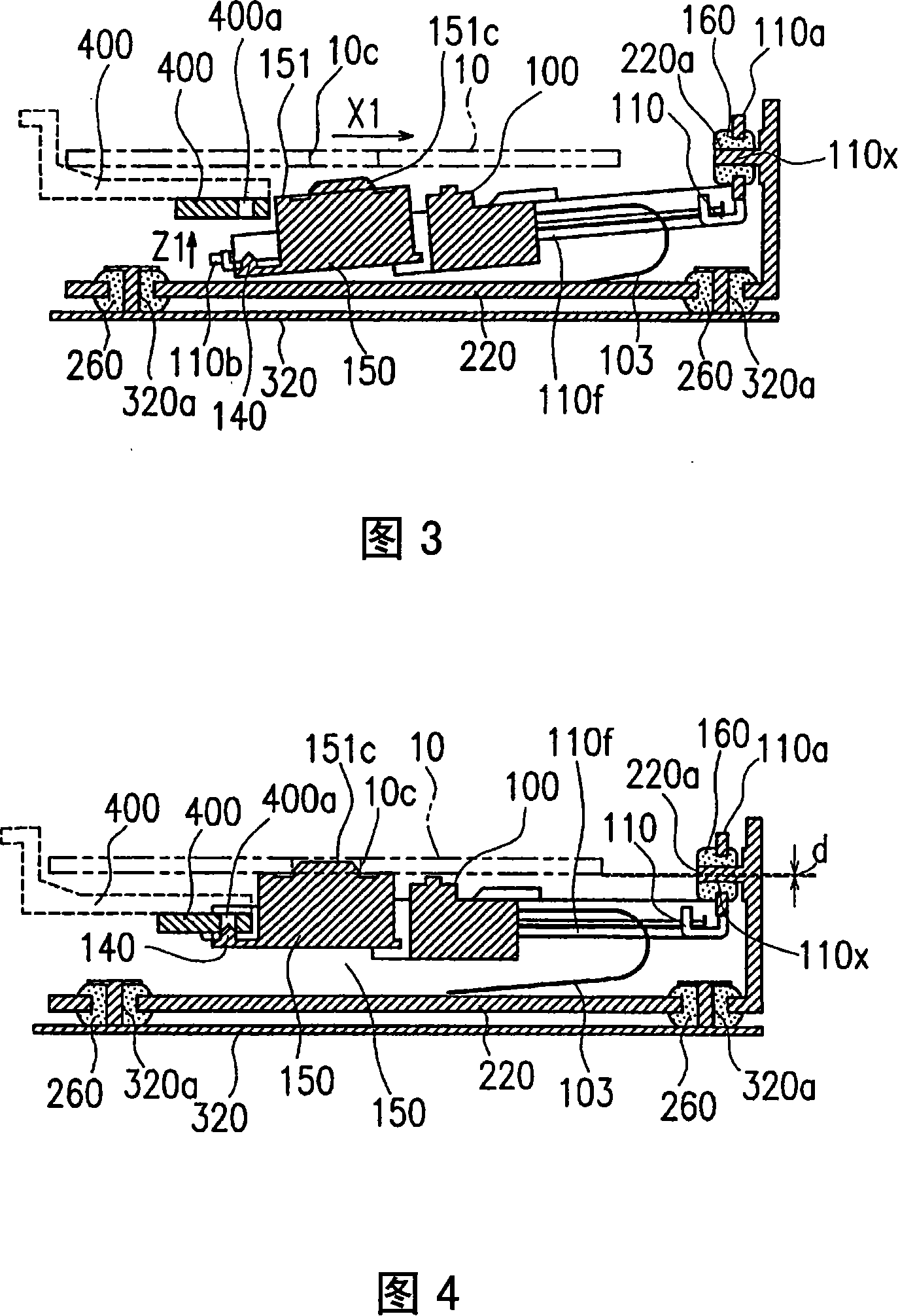
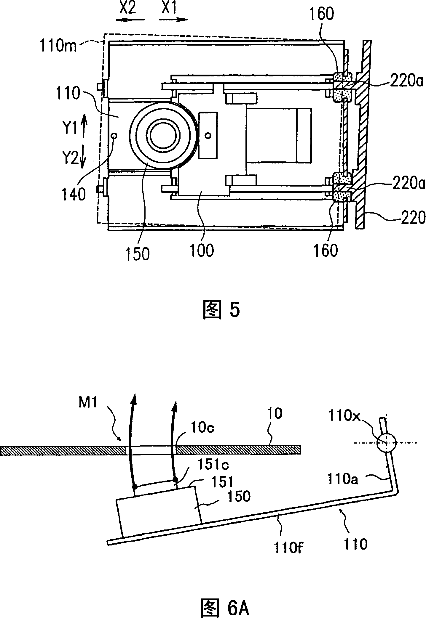
[0041] Next, a first embodiment of the disk drive of the present invention will be described with reference to FIGS. 1 to 9 .
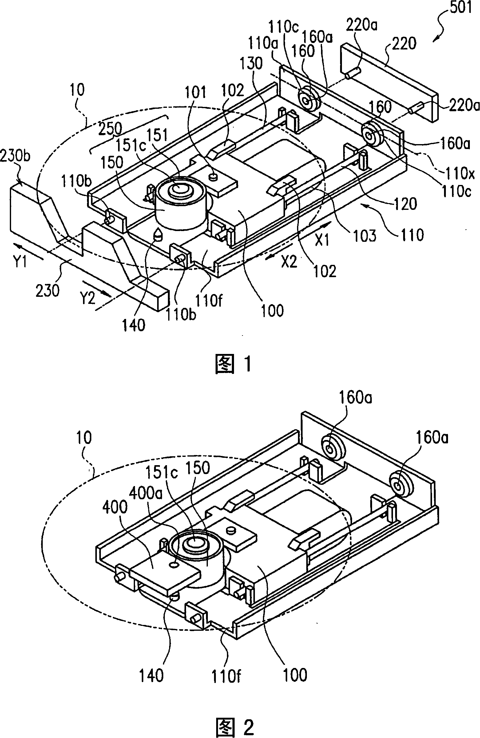
[0042] FIG. 1 is an exploded perspective view showing main parts of a disk drive 501 .
[0043] The disk device 501 has a pickup 100 , a mechanical chassis 220 , a rotation drive unit 250 , a pickup support 110 , and a pickup lifter 230 .
[0044] The pickup 100 records information on the disc-shaped recording medium 10 or reproduces information recorded on the recording medium 10 . Recording and reproduction of information can be performed optically or magneto-optical. For example, the recording medium 10 is CD, DVD, BD, or the like. In this case, the pickup 100 has an objective lens 101 , and light having a wavelength corresponding to the type of the recording medium 10 is emitted from the objective lens 101 . In addition, light reflected from the recording medium 10 is received by the objective lens 101 . The pickup 100 has only to be able to perf
no. 2 Embodiment approach
[0083] Next, a second embodiment of the disk drive of the present invention will be described with reference to FIGS. 10 and 11 .
[0084] FIG. 10 is a plan view of the main part of the disk device 502 viewed from above.
[0085] In FIG. 10 , the same reference numerals are assigned to the same components as those in the first embodiment. The disk device 502 has a rotation drive unit, a pickup 100 , a pickup support 210 , and a chassis 220 . In the disk drive 502, the position of the standing wall of the pickup support 210 is different from that of the first embodiment. Specifically, the pickup support body 210 includes a bottom 210 that supports the rotary drive unit and the pickup 100, and a pair of standing walls 210a.
[0086] The standing walls 210 a stand up from the bottom 210 f and face each other in a direction transverse to the moving direction of the pickup 100 . Fig. 11 is a side view of the standing wall 210a.
[0087] Similar to the first embodiment, a hole 210c
PUM
 Abstract
Description
Claims
Application Information
 - R&D Engineer
- R&D Manager
- IP Professional
- Industry Leading Data Capabilities
- Powerful AI technology
- Patent DNA Extraction
Browse by: Latest US Patents, China's latest patents, Technical Efficacy Thesaurus, Application Domain, Technology Topic.
© 2024 PatSnap. All rights reserved.Legal|Privacy policy|Modern Slavery Act Transparency Statement|Sitemap