Embroidery machine

A technology of embroidery machine and embroidery head, which is applied in the direction of sewing machine components, textiles and papermaking, sewing equipment, etc., to achieve the effect of increasing machine efficiency and speed

Inactive Publication Date: 2008-05-07
托马斯·米勒
View PDF5 Cites 2 Cited by
  • Summary
  • Abstract
  • Description
  • Claims
  • Application Information

AI Technical Summary

Benefits of technology

The technical effect described in this patented design relates to improving the performance of a multi -head type of embodiment of a printing press called a loop carrier (LC) holder frame. By connecting multiple holders instead of just one, more flexibility may be provided during different stages within the printer's overall operation. Additionally, there is no longer physical connection between certain parts of the LC holder frame due to the lack of wires needed for signal transmission. Overall, these improvements improve the functionality and durability of the print engine itself while minimizing problems associated with conventional methods such as intermeshing fabrics or changing threads.

Problems solved by technology

This patent describes various technical problem addressed during manufacturing industrial machining equipment: Existing designs require multiple motors and complicated mechanisms to achieve desired movement while reducing induced vibration caused by these factors.

Method used


Image

  • Embroidery machine
  • Embroidery machine
  • Embroidery machine

Examples


Embodiment Construction

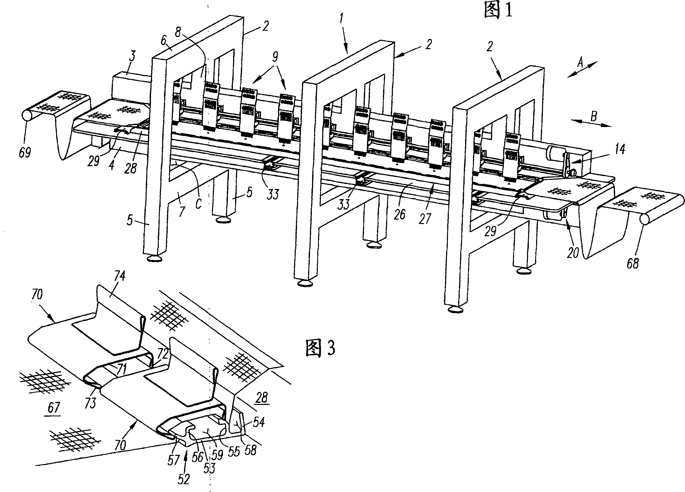
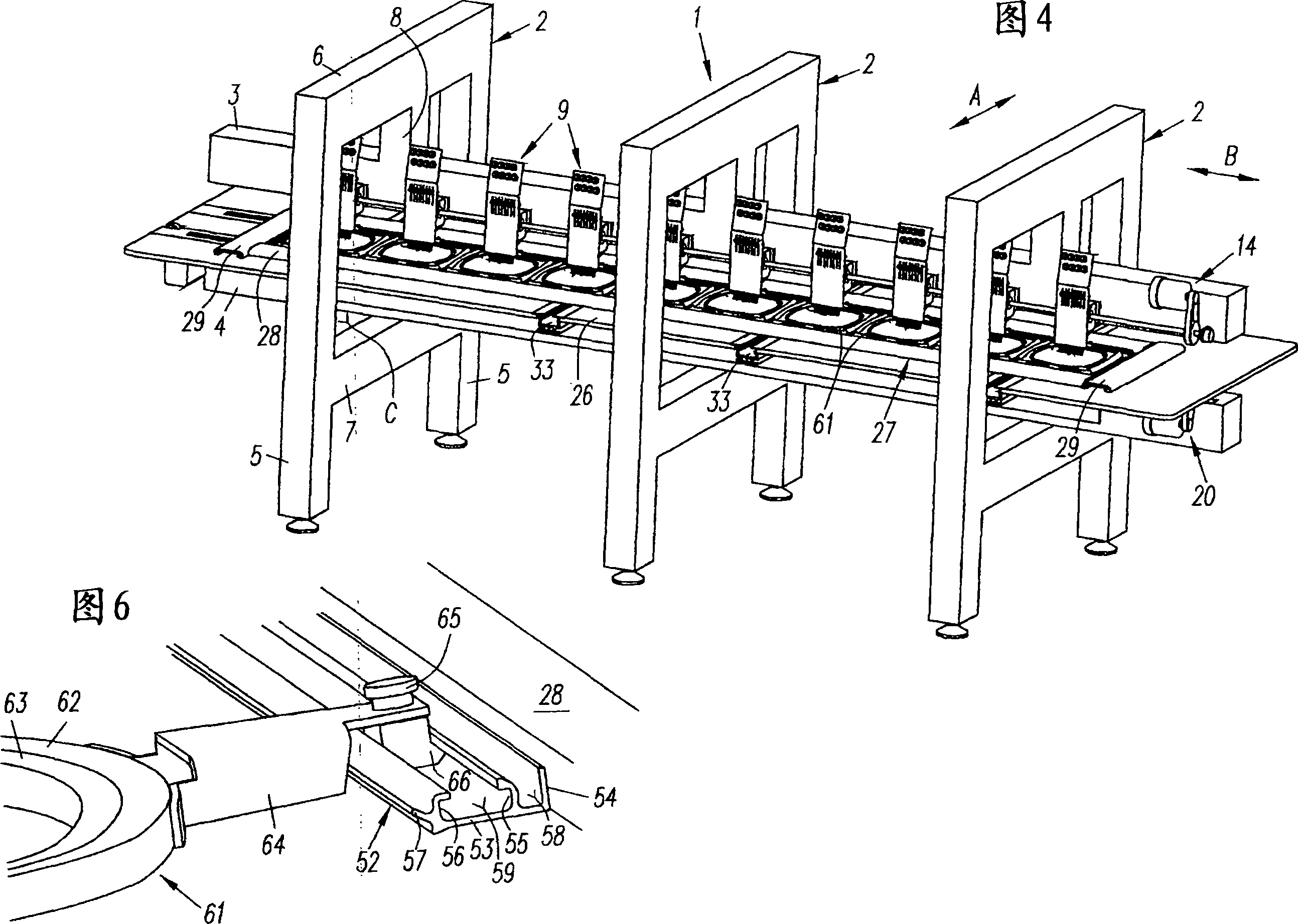
[0023] In the multi-head embroidery machine described in Figures 1 and 4, the frame 1 basically includes three retaining frames 2 arranged in the transverse direction A, forming a bridge and relatively spaced apart, and including an upper supporting beam 3 and an The lower support beams 4 , which run at a distance parallel to the upper support beam, both extend in the longitudinal direction B .

[0024] The holding frame 2 comprises two vertical struts 5 , an upper beam 6 and a lower beam 7 . Each upper cross member 6 has a downwardly directed middle part 8 . The upper support beam 3 is fastened to the lower end of the middle part 8 in such a way that it is at a distance from the underside of the upper transverse beam 6 . The lower support beam 4 instead lies directly on the upper side of the lower cross beam 7 and is likewise firmly connected thereto. The mutually facing inner sides of the vertical struts 5 have a relative distance which simultaneously corresponds to the clear


PUM


Abstract

Multiple head embroidering (EB) machine with (a) machine support (1) consisting of upper carrier beam (3) for EB heads (9) with vertically movable needles (12) and parallel lower carrier beam (4) for support plate (26) and gripper units, (b) drive systems (14, 20) for heads (9) and grippers and (c) feed system (32) for EB frame carrier (27) lying on support plate and movable in longitudinal and transverse directions (B, A), carrier beams are fixed on several bridge-type holding frames (2), having clearances (C) corresponding to maximum allowable transverse movement of EB frame carrier (27).

Description


Claims


Application Information

Patent Timeline
Owner 托马斯·米勒
Why Eureka
Try Eureka