Measuring apparatus

A measuring device, current measurement technology, applied in the direction of measuring device, measuring electric variable, measuring current/voltage, etc.

Inactive Publication Date: 2009-07-15
SIEMENS AG
View PDF0 Cites 12 Cited by
  • Summary
  • Abstract
  • Description
  • Claims
  • Application Information

AI Technical Summary

Benefits of technology

This patented technology makes it possible for an electrical device like a metering unit to transmit measurement values wirelessly without being affected by external factors such as water damage from rainwater. It also includes a mechanism where each part of the system moves smoothly during use while still maintains contact over time. Overall, these technical improvements make wireless communication more reliable and efficient compared to traditional methods used at home.

Problems solved by technology

The technical problem addressed in this patented text relates to how to accurately detect AC signals without introducing errors due to variations from other sources such as disturbances during transmission. Magnetoinductive devices have been developed but they require specialized equipment and can also introduce error factors if placed too near them.

Method used


Image

  • Measuring apparatus
  • Measuring apparatus
  • Measuring apparatus

Examples


Embodiment Construction

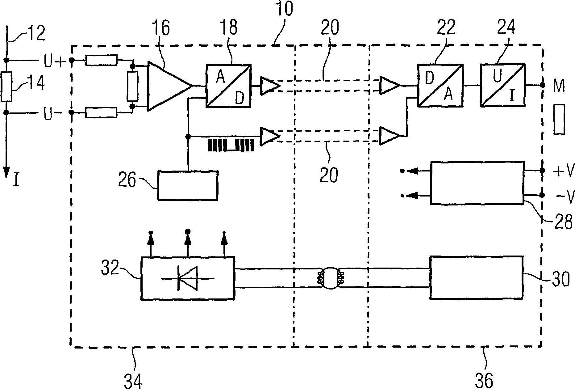
[0029] figure 1 Shown is a measuring device 10 known from the prior art for measuring a current I flowing through a conductor 12 (current measurement). The basis of this known measuring device is a shunt resistor 14 present on a lead 12, the voltage drop across which is measured and transmitted via a differential amplifier 16 to an analog / digital converter 18, from where The coded data of the measured current intensity is transmitted sequentially (for example via the optical waveguide 20 ) to a digital-to-analog converter 22 and from there to a voltage-current transformer 24 . Furthermore, the device 10 comprises an oscillator 26, a voltage regulator 28, a sine wave generator 30 and a rectifier / filter 32 fed by said sine wave generator, said rectifier / filter being used for power supply. The measuring device 10 is divided overall into a first part 34 and a second part 36, wherein the first part 34 functions as a sensor and is spatially allocated to the conductor 12, and the


PUM


Abstract

A measuring apparatus (10), in particular for measuring current, is provided, having a sensor (40) and an evaluation device (42) which is coupled or can be coupled thereto, in which said coupling is effected contactlessly, in particular by means of a transponder interface (44, 46), so that on the one hand current can be measured in a reaction-free manner, wherein on the other hand the resulting measuring apparatus (10) can be used in a particularly flexible and versatile manner on account of the manoeuvrability of the components with respect to one another and on account of the relatively large possible distance between the two parts of the transponder interface (44, 46).

Description


Claims


Application Information

Patent Timeline
Owner SIEMENS AG
Why Eureka
Try Eureka