Luminous device, cooling method thereof and projector

A light-emitting device and cooling method technology, applied in the field of projectors, can solve the problems of loud fan noise, LED light source damage, high heat generation of LED light source, etc., to achieve the effects of reducing noise, avoiding light source damage, and reducing reaction time

Inactive Publication Date: 2009-12-30
QISDA OPTRONICS (SUZHOU) CO LTD +1
View PDF0 Cites 12 Cited by
  • Summary
  • Abstract
  • Description
  • Claims
  • Application Information

AI Technical Summary

Benefits of technology

This technology helps improve the efficiency at which heat generating devices are cooled by reducing their response times while also avoids damage caused when detectors use higher voltages for safety purposes or accurately monitor temperatures during operation. By controlling this process based on factors like ambient air conditions (temperature) and how well it works over time, these technical improvements help protect against harmful environmental impacts such as excessive humidity and debris accumulation that could cause electrical arcs between components within an LED lamp assembly.

Problems solved by technology

This patented technical problem addressed by the current methods described in the previous paragraph relates to improving the efficiency of air conditioners that circulate warm indoor spaces through convection or radiation techniques without causing excessive noise levels caused by increasing fan speeds too quickly when compared to other systems.

Method used


Image

  • Luminous device, cooling method thereof and projector
  • Luminous device, cooling method thereof and projector
  • Luminous device, cooling method thereof and projector

Examples


Embodiment Construction

[0018] In order to have a further understanding of the purpose, structure, features, and functions of the present invention, the following detailed descriptions are provided in conjunction with the embodiments.

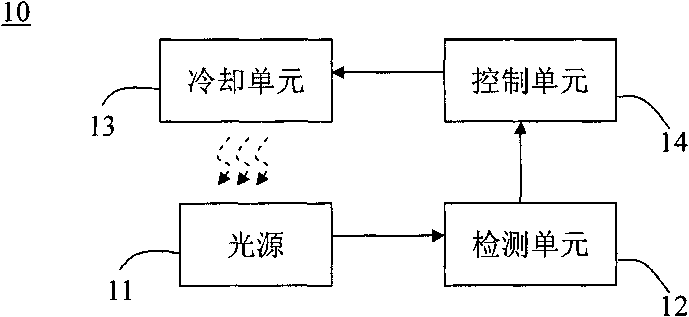
[0019] See figure 1 , figure 1 It is a schematic diagram of a light emitting device 10 according to an embodiment of the present invention. The light emitting device 10 includes a light source 11 , a detection unit 12 , a cooling unit 13 and a control unit 14 . The detection unit 12 is connected to the light source 11 for detecting the current value I and the voltage value V of the light source 11 . The cooling unit 13 is disposed near the light source 11 for cooling the light source 11 . The control unit 14 is disposed between the detection unit 12 and the cooling unit 13 , and adjusts the cooling unit 13 according to the current value I and the voltage value V. In an embodiment, the light source 11 may be a light emitting diode (LED), a light bulb, or the like.


PUM


Abstract

The invention relates to a luminous device, a cooling method thereof and a projector, wherein the luminous device comprises a light source, a detection unit, a cooling unit and a control unit, wherein the detection unit is connected to the light source and used for detecting current value and voltage value of the light source; the cooling unit is arranged close to the light source and used for cooling the light source; and the control unit is arranged between the detection unit and the cooling unit, and adjusts the cooling unit according to the current value and the voltage value. The invention can effectively reduce the response time and noise of the cooling unit, and avoid the damage to light sources with high heat value in the luminous device.

Description


Claims


Application Information

Patent Timeline
Owner QISDA OPTRONICS (SUZHOU) CO LTD
Why Eureka
Try Eureka