Confirmation method of wave beam weight and device
A technology for determining a method and a device, which is applied in the field of communication, can solve problems such as quantization errors and large channel overhead, and achieve the effects of avoiding quantization errors and reducing channel overhead
- Summary
- Abstract
- Description
- Claims
- Application Information
AI Technical Summary
Benefits of technology
Problems solved by technology
Method used
Image

Examples
Embodiment 1
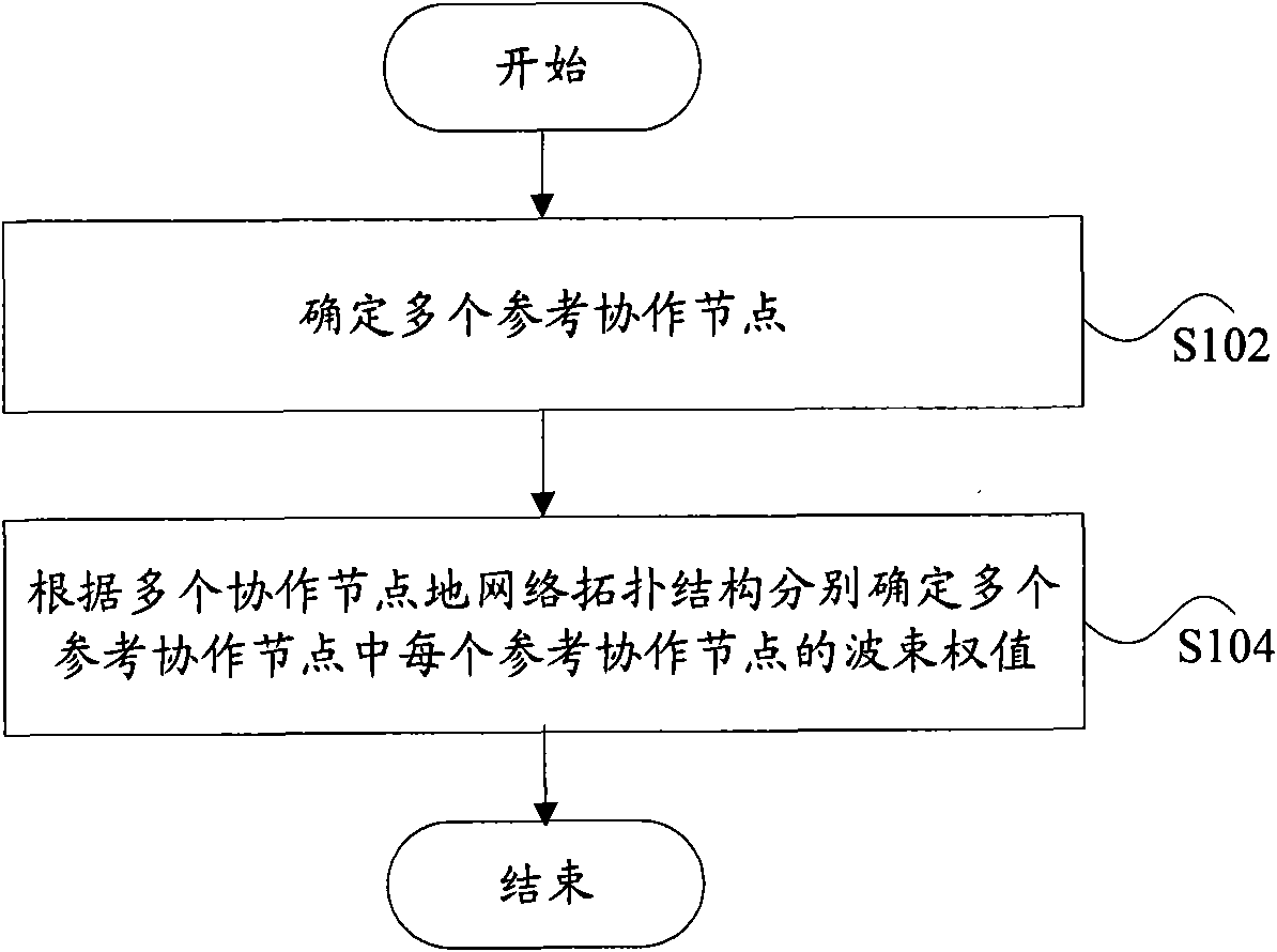
[0045] According to an embodiment of the present invention, a method for determining a beam weight is provided. figure 1 is a flowchart of a method for determining beam weights according to an embodiment of the present invention, such as figure 1 As shown, the method includes the following steps:
[0046] Step S102, determine multiple coordinating nodes (refer to coordinating nodes); in the current communication network, users (ie, the above-mentioned target users) need to perform power feedback to the base station, based on this, the coordinating nodes mentioned here refer to is the coordinating node whose received feedback power from the user is within a predetermined range;
[0047] Step S104, respectively determining the beam weight of each of the multiple coordinating nodes according to the network topology of the multiple coordinating nodes.
[0048] Through the technical solution provided by the embodiment of the present invention, the beam weight value of each cooperati
example 1
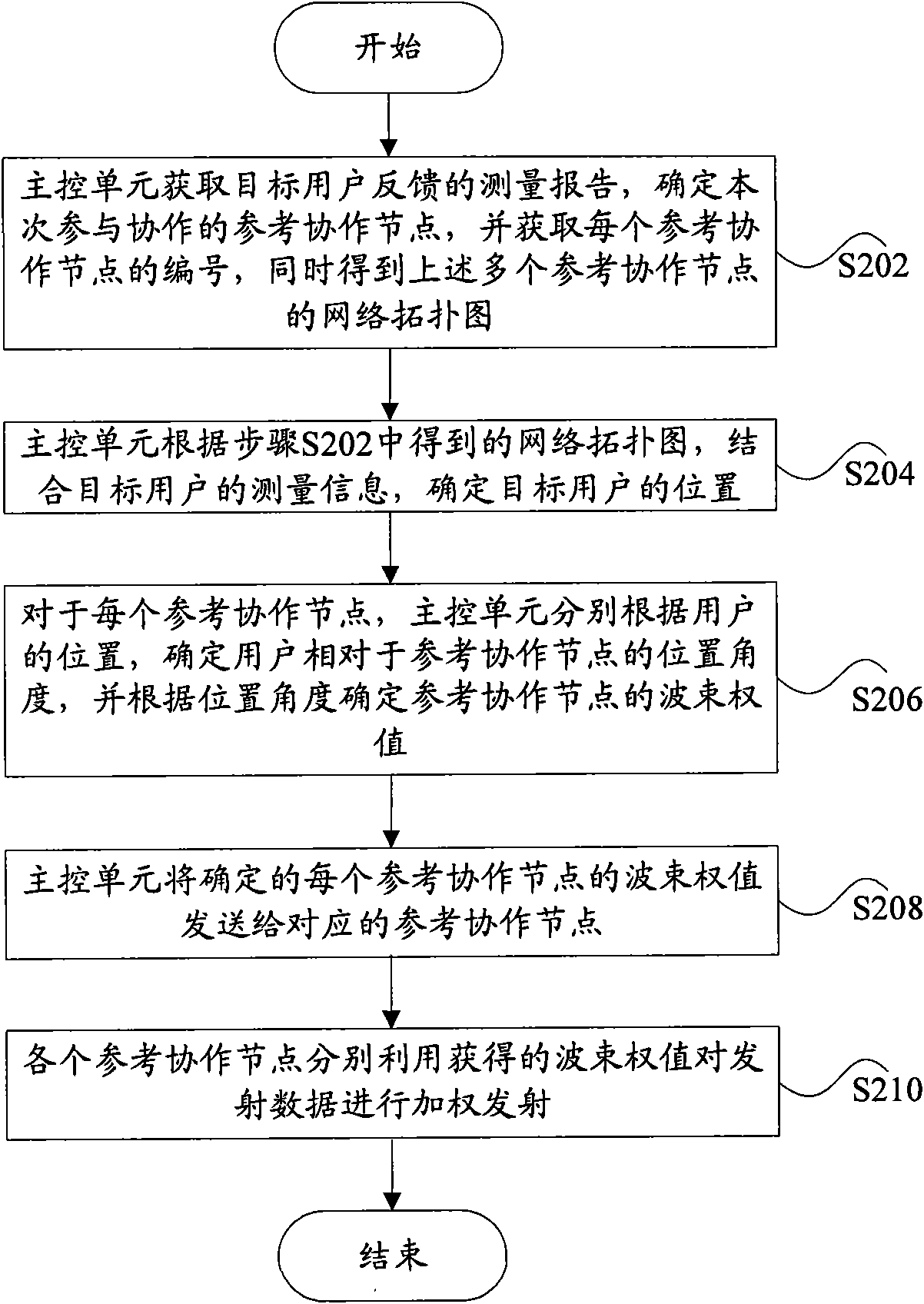
[0060] figure 2 It is a detailed processing flowchart of the method for determining beam weights according to the method embodiment of the present invention, as figure 2 As shown, the method includes the following steps (step S202, step S212):
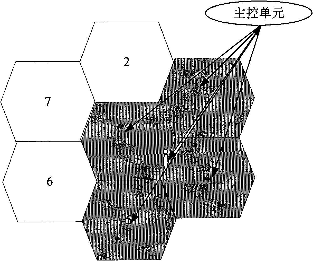
[0061] Step S202, the main control unit obtains the measurement report fed back by the target user (that is, the user mentioned above), and when it is determined that the cooperative MIMO is satisfied, multiple cooperative nodes whose feedback power is within a predetermined range can be determined as the primary Participate in the collaboration node of collaboration for the second time, and obtain the serial number of each collaboration node, obtain the network topology diagram of above-mentioned multiple collaboration nodes simultaneously (as shown in Fig. 3 (a), will be described below);
[0062] In step S204, the main control unit determines the location of the target user according to the network topology diagram obtained in step
example 2
[0073] Figure 4 It is a detailed processing flowchart of the method for determining beam weights according to the method embodiment of the present invention, as Figure 4 As shown, the method includes the following steps:
[0074] Step S402, the same as the above step S202;
[0075] Step S404, the main control unit sends the serial number and the network topology map of the cooperative node determined in step S402 to the above-mentioned multiple cooperative nodes;
[0076] Step S406, each coordinating node determines the position angle of the user relative to itself according to the position of the user, and then determines the beam weight of the coordinating node according to the determined position angle;
[0077] After the beam weight is determined, each cooperative node can also adjust the beam weight of the cooperative node according to the distance between the user and the user; in addition, it can also adjust the beam weight of the cooperative node according to the load
PUM
 Abstract
Description
Claims
Application Information
 - R&D Engineer
- R&D Manager
- IP Professional
- Industry Leading Data Capabilities
- Powerful AI technology
- Patent DNA Extraction
Browse by: Latest US Patents, China's latest patents, Technical Efficacy Thesaurus, Application Domain, Technology Topic.
© 2024 PatSnap. All rights reserved.Legal|Privacy policy|Modern Slavery Act Transparency Statement|Sitemap