Auto-switch-on system on basis of power grid dispatching and implementation method thereof

A technology of power grid dispatching and implementation method, which is applied in the direction of information technology support system, electrical components, circuit devices, etc., can solve the problems that the substation equipment cannot be automatically switched on and overloaded, so as to reduce construction costs, improve reliability, Guarantee the effect of reasonable distribution

Inactive Publication Date: 2010-05-12
NARI TECH CO LTD
View PDF0 Cites 7 Cited by
  • Summary
  • Abstract
  • Description
  • Claims
  • Application Information

AI Technical Summary

Problems solved by technology

The above-mentioned standby automatic switching device or system only collects the bus voltage, line current and circuit breaker position in one substation, completes the tripping and closing of the circuit breaker in the su

Method used


Image

  • Auto-switch-on system on basis of power grid dispatching and implementation method thereof
  • Auto-switch-on system on basis of power grid dispatching and implementation method thereof

Examples


Embodiment Construction

[0018] An embodiment of the present invention will be further described below in conjunction with the accompanying drawings.

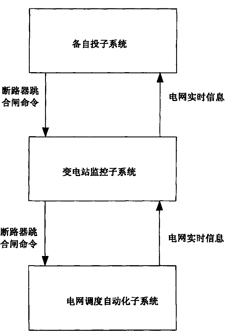
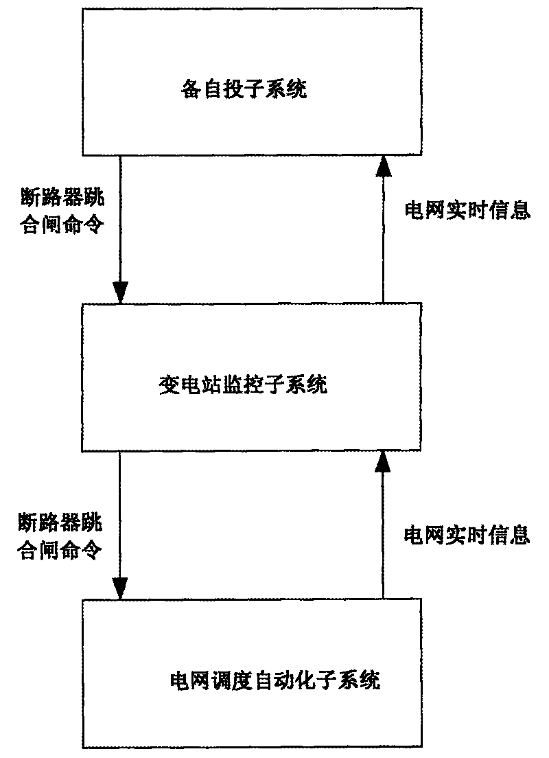
[0019] In this embodiment, the backup and automatic switching system based on grid dispatching includes the OPEN3000 grid dispatching automation subsystem, the NS2000 substation monitoring subsystem, and the backup and automatic switching subsystem implemented with graphical software functions.

[0020] The standby automatic switching system realizes the backup automatic switching and overload switching functions of the power grid, including the backup automatic switching and overload switching functions between substations, and the backup automatic switching and overload switching functions within the substation.

[0021] The OPEN3000 power grid dispatching automation subsystem collects real-time information of the entire network, and transmits it to the NS2000 substation monitoring subsystem through the Ethernet in the form of 104 protocol, and the NS200


PUM


Abstract

The invention discloses an auto-switch-on device on the basis of power grid dispatching and an implementation method thereof. The system comprises a power grid dispatching automation sub-system, an auto-switch-on sub-system and a transformer substation monitoring sub-system, and is characterized in that the power grid dispatching automation sub-system is connected with the transformer substation monitoring sub-system via a communication network; and the transformer substation monitoring sub-system is connected with the auto-switch-on sub-system via a computer cache. The system and the implementation method of the invention can fulfill the functions of auto-switch-on and overload cutoff between and in the transformer substations and substitute for various existing auto-switch-on devices and systems which are already in use, thereby reducing the construction cost of the power grid, effectively improving the operational reliability thereof and guaranteeing the reasonable load distribution thereof.

Description


Claims


Application Information

Patent Timeline
Owner NARI TECH CO LTD
Why Eureka
Try Eureka