Transformer of high-frequency spark vacuum detector

A detector and transformer technology, applied in the direction of transformer/inductor coil/winding/connection, etc., can solve the problems of high material consumption, large volume, easy to burn, etc., to reduce magnetic flux leakage, compact structure, and improve the efficiency of electromagnetic induction. Effect

Inactive Publication Date: 2010-08-11
周祥荣
View PDF5 Cites 0 Cited by
  • Summary
  • Abstract
  • Description
  • Claims
  • Application Information

AI Technical Summary

Problems solved by technology

[0002] The transformer of the existing high-frequency spark vacuum detector generally adopts the traditional transformer structure, which includes an iron core with a rectangular frame structure, and a primary wire package and a secondary wire are

Method used


Image

  • Transformer of high-frequency spark vacuum detector
  • Transformer of high-frequency spark vacuum detector
  • Transformer of high-frequency spark vacuum detector

Examples


Embodiment Construction

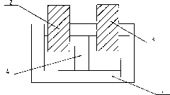
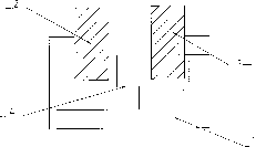
[0009] Such as figure 1 As shown, the transformer includes a rectangular iron core 1, and a primary wire package 2 and a secondary wire package 3 are wound side by side on one side frame of the rectangular iron core, and a choke The iron core 4 is separated, and the choke iron core is connected between the frame where the two wire packages are located and the frame on the opposite side.

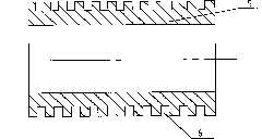
[0010] The primary wire package and the secondary wire package are composed of a bobbin 5 and a coil wound on the bobbin, and the wires are as figure 2 As shown, a plurality of winding slots 6 separated by partitions are arranged side by side on the periphery of the coil bobbin 5, and the coil is wound on the coil bobbin slot by slot.


PUM


Abstract

The invention relates to a component structure of a detector for detecting the vacuum degree by using high-frequency sparks, in particular to a transformer of a high-frequency spark vacuum detector. The transformer comprises a rectangular iron core; a primary solenoid and a secondary solenoid are wound on a frame at one side of the rectangular iron core in parallel; and the primary solenoid is separated from the secondary solenoid by a choke iron core which is connected between an iron frame that the two solenoids are arranged and a frame at the opposite side. Since the primary solenoid and the secondary solenoid are coupled at the same side of the frame of the iron core, the invention not only has compact structure and saves materials, but also reduces the flux leakage and improves the electromagnetic induction effect; especially under the condition that the output end generates short circuit, the current of a core device of the traditional high-frequency spark vacuum detector rapidly raises and heats; and however, a choke magnetic filed is added in the transformer, the current not only cannot raise, but also can be rapidly reduced, thereby the transformer is not easy to burn down and the service life of the transformer can be prolonged.

Description


Claims


Application Information

Patent Timeline
Owner 周祥荣
Why Eureka
Try Eureka